W-AIR Network Admin Guide - Sync over LAN
This guide leads you through installation of W-AIR Base Sync Plus and setting up a W-AIR DECT Network in which the bases sync over LAN.
W-AIR Base Sync Plus and Sync Plus Outdoor support starts from WMS 5.01.
Useful links:
- W-AIR System Datasheet
- W-AIR Network Admin Guide - Sync over the air
- W-AIR Small Business - Admin Guide
- /wiki/spaces/DOC/pages/30279971
Updated: January 2023
Permalink: https://wildix.atlassian.net/wiki/x/PgjOAQ
Watch the video tutorial about setting up a W-AIR Multicell Network (registration is required):

Description
System architecture
W-AIR is a Wildix cordless solution. The system supports auto-provisioning enabling instant connection to the Wildix PBX. Due to high scalability, new components are quickly and easily integrated to guarantee the better performance.
Wildix W-AIR system uses the wireless technology CAT-iq (Cordless Advanced Technology – Internet quality).
The architecture consists of three components:
1. Base station - an essential component of a DECT system. Wildix W-AIR base stations:
- Multicell base stations: W-AIR Base Sync Plus, W-AIR Base Sync Plus Outdoor
- Single Cell base station: W-AIR Base Small Business. Documentation: W-AIR Small Business - Admin Guide, /wiki/spaces/DOC/pages/30279971
2. Repeater - extends the signal coverage of the base station.
3. Cordless endpoints:
Wildix W-AIR handsets: W-AIR Basic2, W-AIR LifeSaver, W-AIR Med, W-AIR Office and W-AIR Headset. Follow the online Guides to get detailed information: W-AIR DECT Handsets Guide, W-AIR Headset Guide.
Multicell network scalability and features
Sync over LAN with W-AIR Base Sync Plus/ W-AIR Base Sync Plus Outdoor:
- LAN PTP Sync or Sync over the air (for sync over the air, refer to W-AIR Network Admin Guide - Sync over the air)
- Up to 16000 users per system
- Up to 30* users registered to 1 base station
- Up to 4000 bases per system
- Up to 8 concurrent calls** per base
- Up to 8 concurrent handovers per base
- Up to 3 repeaters per base
- Up to 50 bases - 3 repeaters
- 50-125 bases - 1 repeater
- More than 125 bases - no repeater
- Up to 5 concurrent calls per repeater
- Up to 100 repeaters per system
- Base station indoor range: 50 m; outdoor range: 300m
.png?version=1&modificationDate=1671801231794&cacheVersion=1&api=v2&width=600&height=320)
*Note: by default W-AIR system supports up to 20 devices, to increase the number to 30 devices, use Custom Provisioning parameter, described in this document.
** Enabling PTT feature (Push-to-talk) on W-AIR handsets reduces the number of available channels on each base station to 6.
Advantages of LAN PTP Sync
IEEE1588 is also named Precision Time Protocol (PTP). The implemented standard is IEEE1588-2008.
- PTP is using multicast for message transport
- A multicast IP and Port has been standardized
- PTP defines a domain number embedded in each datagram, which makes it is possible to run 128 parallel systems
- PTP defines a PTP-Primary role and a PTP-Secondary role; the role can be auto negotiated or forced by configuration
- Only one primary device can be active within a PTP domain.
- The device with the primary role dictates the synchronization, and the devices with the secondary role try to follow as close as possible
- PTP use the IP-network to keep the sync between the devices
Sync over the air: base stations must be able to see each other:
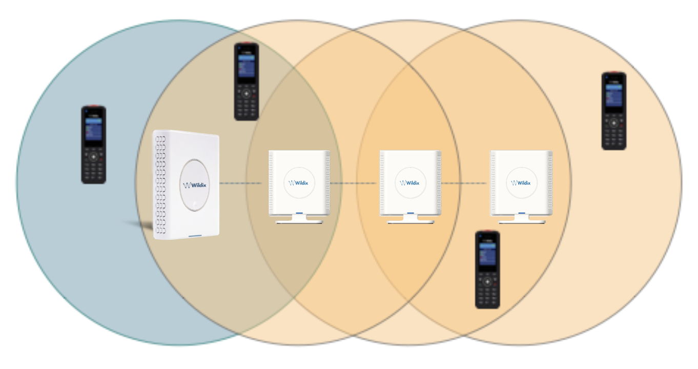
Sync over LAN: base stations are not required to see each other, roaming and handover can be performed, as long as the handset can see both base stations:

As a result:
- Easier deployments
- Better coverage
- Less Base Stations
Network requirements
In order to minimize the impact from other devices on the network, the following requirements to the network infrastructure are listed:
- A maximum number of 3 cascaded Ethernet switches are supported between the primary device and secondary devices
- Only switches, which fulfil the requirements regarding Ethernet synchronization according to IEEE1588, are recommended and officially supported
- All base stations must be connected to a dedicated DECT VLAN
- The DECT VLAN must be configured to the highest priority in all the switches that are connected to the DECT infrastructure
- The backbone network load should not exceed 50 percent of the total link capacity
- The Ethernet switch must be able to use DSCP as QoS parameter
The network must support multicast datagrams from IEEE1588
Please note that Wildix switches are EOL!
Make sure to select the switches that follow the specifications described above.
Connecting 3 Repeaters in a chain:
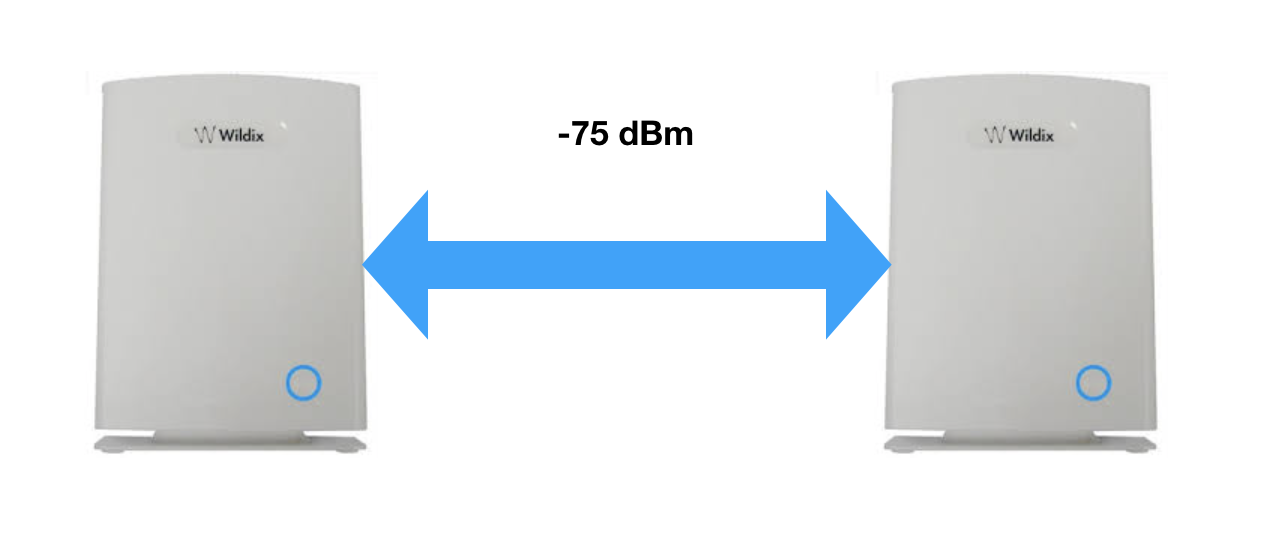
Base Station and Repeater positioning: phone must be able to see both base stations (dBm value must be between -75 and 0):
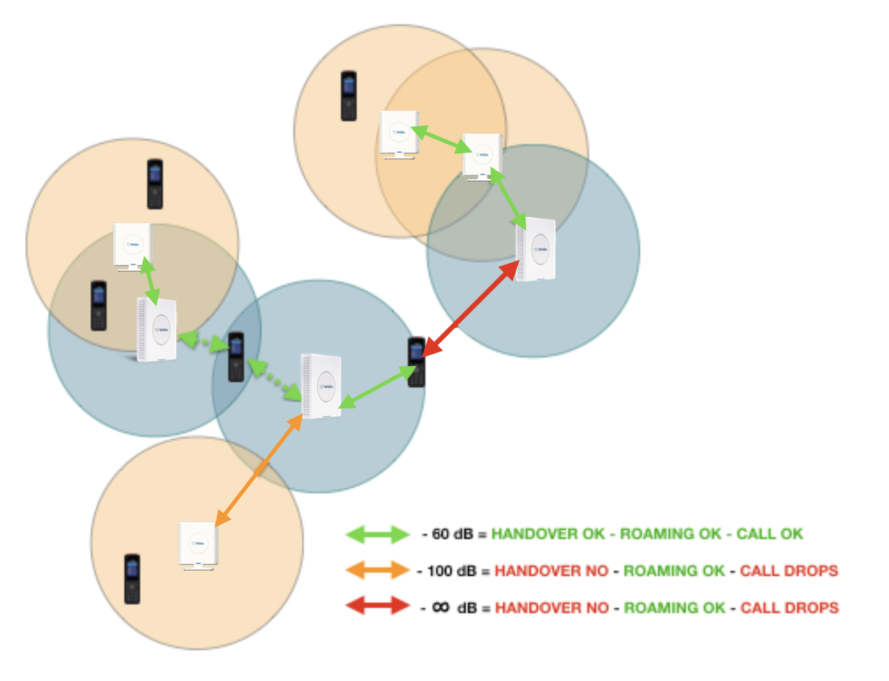
For a good conversation and a correct handover between Bases and their Repeaters the dBm value must be between -75 and 0.
Handover and Roaming
Handover
Handover is a process in which a call is transmitted from one base station to another without interrupting the session.
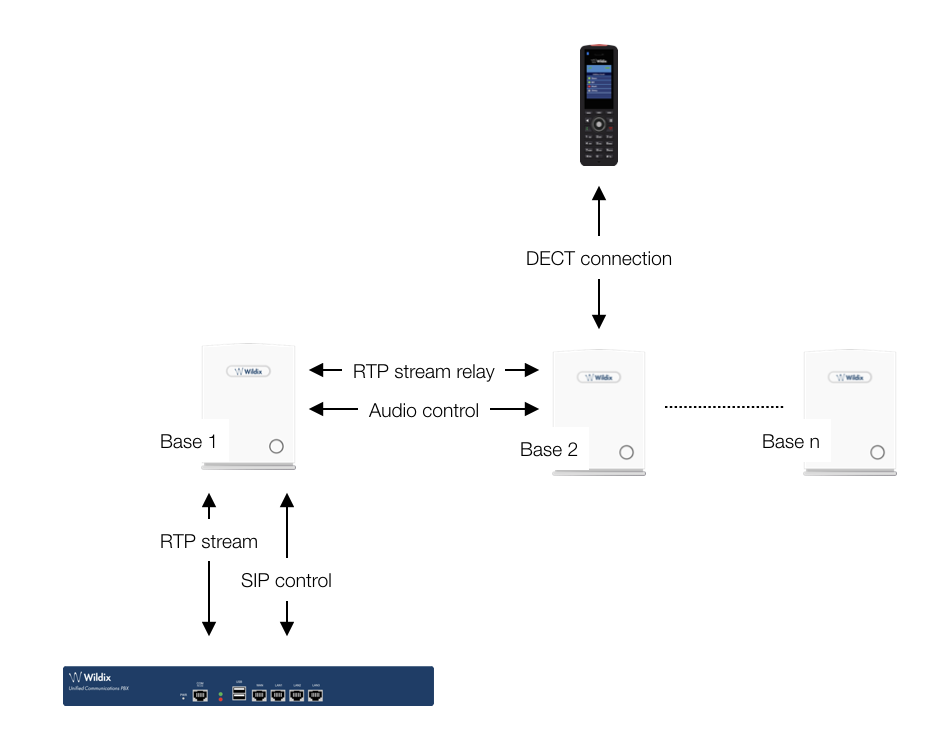
When the call is set up, the handset is located at Base 1. Thus, the DECT communication takes place between the handset and Base 1, and the SIP signalling as well as the RTP stream takes place between Base 1 and the PBX:
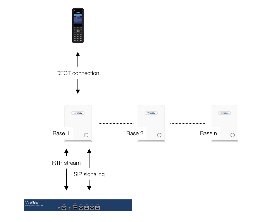
After handover, the handset is located at Base 2, and hence the DECT communication goes on between the handset and Base 2. However, to avoid disruption of the audio, the RTP stream is relayed via the initial base station, since a transfer of the RTP stream to another base may cause the PBX to re-initialize the RTP stream with a small disruption of the RTP stream as consequence. Thus, RTP stream is not affected by the handover, and since the call control also remains at Base 1, SIP signalling is also unaffected, as shown below:
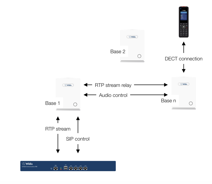
Since the call control and hence the SIP User Agent remains at the initial base station, the SIP registration is also unaffected by the handover. If the handset makes yet another handover, the RTP stream will still be relayed via the base station at which the call was established (Base 1 in our case):
Roaming
By roaming it is meant that the handset moves its SIP and DECT registration from one base station to another base station. Roaming can only be initiated from idle.
Roaming does not immediately result in a new SIP registration, to avoid unnecessary signalling. Therefore, the handset will not perform a new DECT Location Registration until it has resided on the same base station for a defined period of time*. Since the SIP registration is initiated by the completion of the Location Registration, a new SIP registration will also not be done until this procedure has completed on a new base station. Thus, a handset must stay on the same base station before a new SIP registration is made.
*How the period of time after which Location Registration is performed, is defined:
Handsets lose contact to the initial base station due to reset/ power off/ heavy DECT traffic
After 5 minutes but before 5+2 minutes (+2 minutes occur when service connection traffic is signalled at the same time as location registration should take place; in this case the location registration procedure will be delayed)
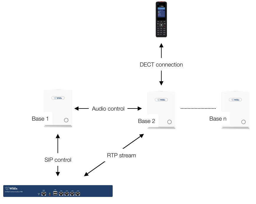
If an incoming call arrives while the handset has moved to another base station (Base 2 in our example) but the new Location Registration was not yet performed, the SIP call will arrive at the initial base station (Base 1 in our example), the RTP stream will be set up between Base 2 and the PBX. Alternatively, in the case of an outgoing call, the SIP call will be established from the initial base station, and the RTP stream will be set up between Base 2 and the PBX:
Deployment considerations
The following radio related issues should be considered before deploying a W-AIR DECT Network:
- Building Penetration: when a signal strikes on a building it is diffracted or absorbed; therefore the signal can be reduced. The amount of absorption depends on the building and its environment, the amount of solid structure
- Interference Sources: other signals can create interferences and weaken the signals of the receiving antennas. These interferences can come from the same network or from the outside. For choosing the optimal position of the Base station and Repeaters, these potential interference sources should be considered before installing a Wildix W-AIR system
Radio/ Cell Range: a suggested distance between two base stations depends on the physical path between them. If the path loss is lessened, e.g. by minimizing the amount of walls/ obstacles on the path, then the signals of the base stations cover more distance. In a typical office building a suggested distance between two base stations is 30-40 m
Do not place base stations close to GSM Media gateways (DaySaver or W01GSM).
Capacity planning
The maximum quantity of calls is indicated in the list below:
- Base stations: up to 8 simultaneous calls
- Repeaters: up to 5 simultaneous calls
Call 76 Feature code (Echo) on your W-AIR Handset to test the voice quality.
Notes:
- The total coverage capacity of a base station and one or more Repeaters is always limited to the capacities of a base station
- A W-AIR network uses an auto-balancing model to increase the number of simultaneous calls, distributing the calls to 2 or more adjacent Base stations
- Simulate the worst environmental conditions (close the doors, turn on the equipment, etc) to perform a realistic test of configuration
- Call 98 Feature code (Conference) on your W-AIR Handset to listen to the music on hold, to test an audio reception quality
- If you enable PTT (push to talk) feature on W-AIR Handset, the number of available channels on each base station is reduced to 6
Network topology
A maximum of three switches is allowed between the base stations.
Please note that Wildix switches are EOL! Make sure to select the switches that follow the specifications described above.
Bad network topology: (there are more than three switches connected in a cascade)
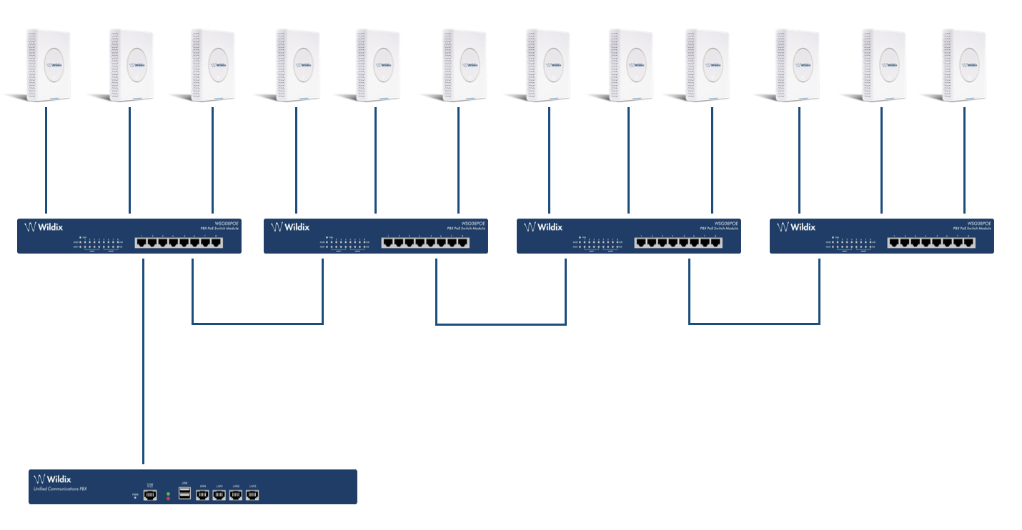
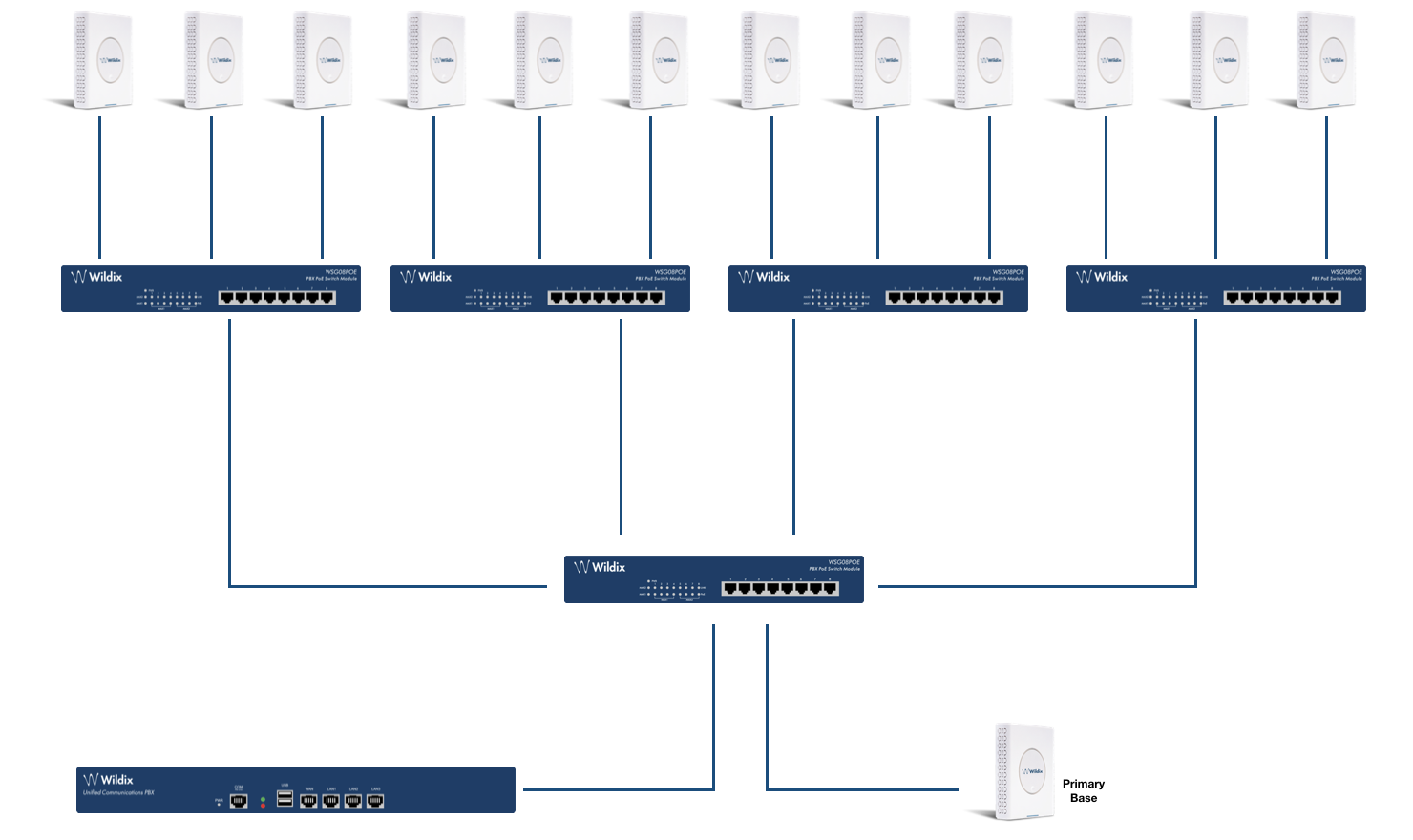
Good network topology: (no more than three switches connected in a cascade)
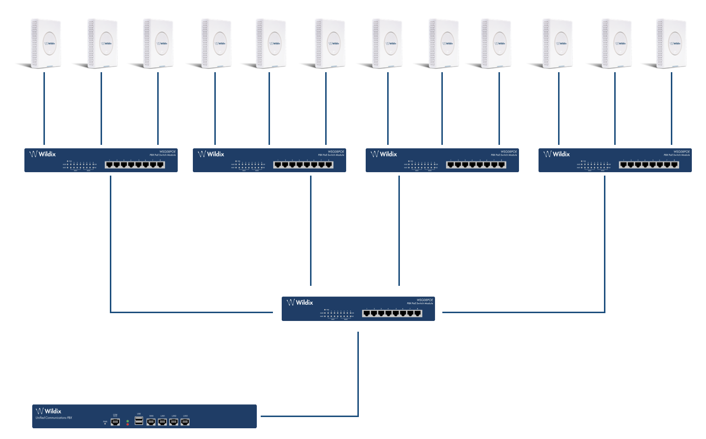
- A maximum number of 3 cascaded Ethernet switches are supported between the primary device and secondary devices
- Only switches that correspond to Ethernet synchronization requirements according to IEEE1588, are supported
- All base stations must be connected to a dedicated DECT VLAN. DECT VLAN must be configured to the highest priority in all the switches that are connected to the DECT infrastructure
- The backbone network load should not exceed 50 percent of the total link capacity
- The Ethernet switch must be able to use DSCP as QoS parameter
- The network must support multicast datagrams from IEEE1588
PTP is sensitive to rapid changes in network delays, thus if the above mentioned rules are not respected, you might run into network delay problems due to the following mistakes:
- Rapid fluctuations in the network delay was caused by a backup job in another VLAN
- The DECT VLAN was not configured to high priority
- The sync offset between the base stations reaching critical levels
Placing the primary base station
The primary base station should be placed in the center, connected to the primary switch:
Site Survey
Requirements
- PoE switches or a 48V PoE power injector. Site survey is possible without network connectivity
- A DHCP server. If you are using Wildix PBX as DHCP Server, go to Settings -> System -> DHCP Server and search for the device among the DHCP leases. Detailed information on configuration: WMS Settings Menu Admin Guide
- A W-AIR base. Reset the base station to the default settings
- A W-AIR handset. Before getting started make sure the handset is fully charged. The handset does not need to be pre-registered to a particular base. Connect the base station to the power injector and turn it on
How to check RSSI level
Follow the steps below:
- Press "Menu" key of the W-AIR handset
- Type *ip* (*47*)
- Use the cursor down/ up to select the base MAC address
- Select the base station to view its RSSI level
Placing the first base station
Follow the steps below:
- Place the W-AIR base station exactly at the desired position and power on the base
- Check RSSI level on the handset
- Use the building plan drawing and check the base station coverage using the Site survey mode of the phone. Mark up acceptable and unacceptable spots on the plan drawing. Take notes of the RSSI levels of the base. Acceptable spots are the ones where the phone shows RSSI levels better than -75 dBm
Follow the steps again to place more base stations
Typically, when the system is installed in the office buildings, hotels or hospitals, there should be both Base stations and Repeaters on several floors to create uniform and complete radio coverage. Open areas can be covered by wide network of Base stations.
Check the Delay and the Jitter
When you have placed several base stations, go to the web interface of the base station → select menu LAN Sync and check the columns "Nwk. Jitter" and "Nwk. Delay". Make sure the values are as little as possible.
Check the Radio Coverage
Handset
- Press "Menu" key of the W-AIR handset (the phone must be registered to the base station)
- Type *service* (*7378423*)
- Select the line Site survey mode
- The phone will show up to 5 bases (RPN) and the coverage value
- Check PP and FP values, they indicate the transmission errors. Empty value or a low number indicates a correct behavior (value 100 = the worst behavior)
Base station
For a good conversation and a correct handover between bases and their Repeaters the dBm value should be between -75 and 0.
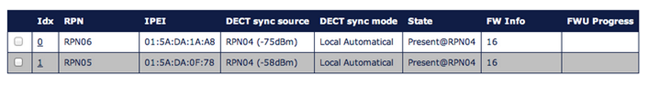
Repeaters
Go to the web interface of a base station and click on Repeaters to see the status and the coverage values of every connected Repeater, check the column DECT sync source to know the value:
Base station/ Repeater Placement Strategy
The antennas of the base stations are close to omnidirectional, thus it is not important how the base stations are directed and how they face each other. There is no single strategy for deploying base stations, but there are some recommendations:
- In the Corridors: base stations/ Repeater should be deployed vertically, preferably in the corridor intersections so that the propagation follows the corridor patterns/ curves. If there are high objects in the area, the base station/ Repeater should be installed above them
- Multi-storey Buildings: base stations and Repeaters can be installed on the opposite sides of the floors to cover the area floor-to-floor. The coverage design cannot rely entirely on floor-to-floor propagation; each case should be verified due to variations in local attenuation patterns
- Large Halls: base stations and Repeaters can be deployed in large halls that contain a central open space area with windows leading to other areas. This provides a good coverage for the rooms in the inner circle on all floors (e.g. hotels). In large halls, Base stations/ Repeaters should be installed vertically in the middle of the space below the drop ceiling
- Mounting Positions: when Base stations and Repeaters are mounted vertically on a wall, the radio coverage in front of these devices is twice as large as the coverage behind them. The base stations should always be mounted higher than the obstructive objects in the area – e.g. minimally 2m above the floor. Repeaters should be installed in the middle of the corridors and small rooms
- Metallic Structures/ Objects: base stations and Repeaters should not be deployed near large metallic objects
- Reinforced Concrete Structures: these structures create a high attenuation factor inside the building. They reduce the radio coverage range of the Base stations and Repeaters thus a higher number of base stations or Repeaters are required in the building. Lighter types of construction materials require fewer base stations since attenuation figures are considerably lower
Base station and repeaters connection and overview
Packing lists
W-AIR Base Sync Plus:
- Mounting screws x 2 and anchors x 2
- Plastic wall mount x 1
- Base station unit x 1
- Power supply adapter is not included (item can be ordered separately, code: PS-WAIR-Base-Sync-Plus - 5 pcs - 5V 2A EU, US, UK - Power Supply for WAIR-Base-Sync-Plus)
W-AIR Base Sync Plus Outdoor:
- Box Top Housing x 1
- Plastic Screws x 4
- Foam Support x 1
- Base station unit x 1
- Wall Mount Bracket x 1
- Mounting Plate x 1
- Screws x 4
- Box Bottom Housing

W-AIR Repeater:
- Power adapter x 1
- Repeater unit x 1
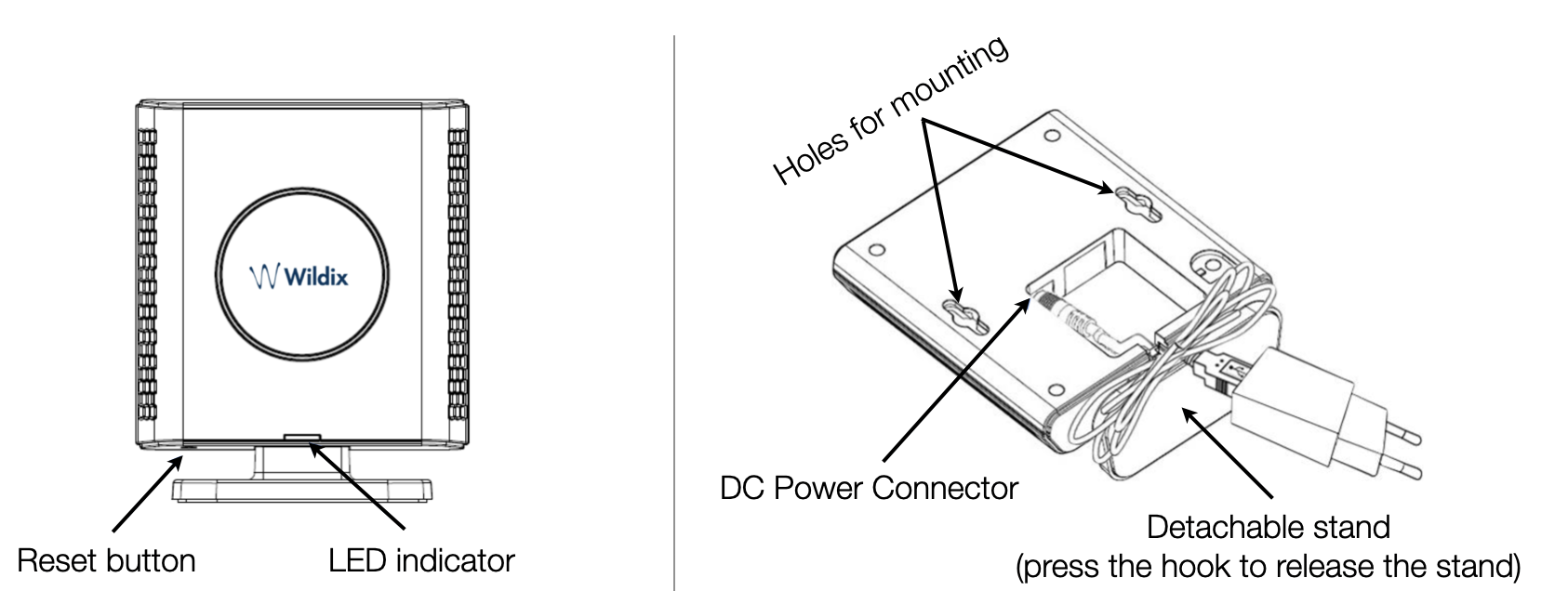
Base station mounting, connection and reset
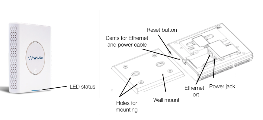
Reset a base station: press the Reset button on the back side for more than 2 seconds.
LEDs of the Base Station
UNLIT | No power in unit |
UNLIT/SOLID RED | Error condition |
BLINKING BLUE | Initialization |
SOLID RED | Factory reset warning or long press in BS reset button |
BLINKING RED | Factory setting in progress |
SOLID BLUE | Ethernet connection available (Normal operation) |
BLINKING RED | Ethernet connect not available OR handset de/registration failed |
SOLID RED | Critical error |
ORANGE | Press reset button of base station |
BLINKING ORANGE | No IP address received |
Mounting instructions
Mount the base unit as high as possible to clear all nearby objects (e.g. office cubicles and cabinets, etc.). Make sure that when you fix the base stations with screws, the screws do not touch the PCB on the unit. Avoid all contacts with any high voltage lines.
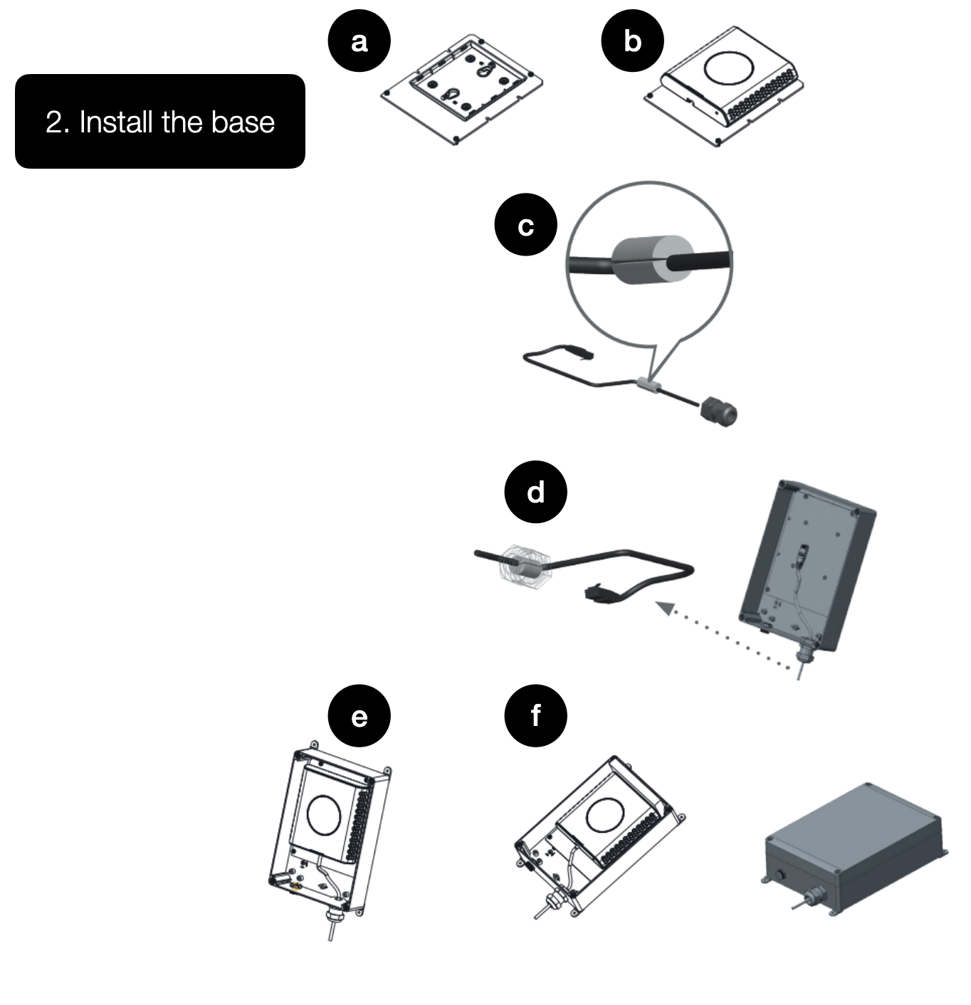
W-AIR Base Sync Plus Outdoor
- Take out the base:
- Unscrew 4 plastic screws to open the Box Top
- Unscrew 4 screws mounted on the Mounting Plate
- Unscrew the 2 screws from the bottom of the base station
- Push the base station upwards to detach it from the Metal Wall Mount Plate
- Install the base:
- Put the LAN cable into the Mounting Plate
- Attach the base station into the mounting plate using two bottom screws
- Insert the cable through the cable bushing and put on the bushing foam
- Insert the cable bushing into the Bottom Housing
- Place the base station into the outdoor Box Housing
- Attach the Box Top Housing, plug in the wall mount nuts

Find Base station IP
On the handset press Menu key followed by the keys: *47* to get the handset into find bases menu. Depending on the amount of powered on bases with active radios and the distance to the base it can take up to minutes to find a base.
- Use the cursor down/up to select the base MAC address for the base
- The base IP address will be shown in the display
The feature is also used for deployment.
Repeaters connection and overview
Repeater connection and reset
Reset a repeater: press and hold the Reset button on the back side for more than 2 seconds (LED turns solid RED and then GREEN with a double pulsation).
LEDs of the Repeaters
| GREEN BLINKING WITH A DOUBLE PULSE | Registration/subscription mode and searching for open base station |
| GREEN BLINKING | Unregistered, searching for a base station |
| SOLID GREEN | Registered to a base station and ready for use - idle |
| SOLID RED | Failed to connect to a base station |
| BLINKING RED | Handset relayed by repeater |
| RED/GREEN BLINKING | Repeater is in recovery mode for one of the following reasons (try to re-assign Repeater to Base station):
|
W-AIR Network configuration
Step 1. Provision base stations
For detailed instructions, refer to Provisioning of Wildix devices - Admin Guide.
Go to menu Devices of the WMS, click +Add and provision the gateway. Provisioned base stations appear in the table of Devices.
Step 2. Create a W-AIR Network
Important:
- W-AIR Network consists of one or more gateways that belong to the same LAN
- In order to be able to configure a W-AIR network, a NTP server is necessary. To configure the gateway to use the NTP server of the PBX, select the gateway and click Edit, then enter the PBX IP address into the line “NTP Server” and click Save
- In case you add a base station that previously functioned as a separate base station or belonged to a different W-AIR network, it’s necessary first to delete the base station, reset it and add it again to the WMS
Follow the steps below:
- Go to the WMS menu Devices -> W-AIR Networks -> click Add
- Enter the Name for your W-AIR Network
Select the gateways from the list on the left and move them to the list on the right. Make sure the Primary base station is the first one on the list (marked with (M))
Limitation: it is impossible to register a W-AIR Headset if the code of W-AIR network is different from "0000" (default code). Workaround: temporarily change the code to default one ("0000") , register and assign the Headset(s), and then change it back to custom one.
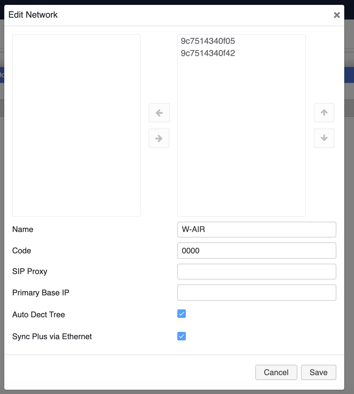
Check off "Sync Plus via Ethernet" option to enable sync over cable
Click Save
W-AIR Network is created:

- Go back to the Devices Menu, select your base/ bases and press Configure/ Sync device button
For CLOUD PBXs, you need to power off the base station and then power it on again (reboot the base station) to apply the new parameters!
Step 3. Register a W-AIR Handset
To register the handset:
- Verify that there is only one active W-AIR Network
- Go to the handset’s main menu
- Select Connectivity
- Select Deregister, enter 0000 as PIN, then press Yes
- Select Register, enter 0000 as Access code, then press OK
- The cordless phone is ready for a new login procedure
To unregister the handset:
- Log out (register to “unknown” account) by calling the Feature Code “Login” (“99” by default)
- Select Deregister in the Connectivity menu of the handset
- Enter the Pin Code “0000”, then press Yes
Step 4. Assign a W-AIR Handset to a User
You can assign W-AIR handset to a user via the handset itself or via WMS (starting from WMS 5.04.20220309.1).
Assigning via the handset
- Switch on your phone and wait till the system assigns you an “unknown account” and the coverage indicator turns active
- Dial the Login Feature Code (“99” by default)
- Enter an extension number and PIN (= the first five symbols of the user WEB password)
How to enter the PIN:
- The keys are alpha-numeric, they allow you to enter both letters and digits, to enter letters: press only once the key corresponding to the letter you need to enter (there is no difference between lowercase and uppercase letters)
- Press * (the star key) to enter any special characters present in the user password, including the symbol "#"
Example: PIN is 4Ag7$Zl@, you have to dial 4247*

Follow W-AIR DECT Handset - User Guide to get more details.
Admin password is also accepted.
Assigning via the WMS
Note: The support starts from WMS 5.04.20220309.1.
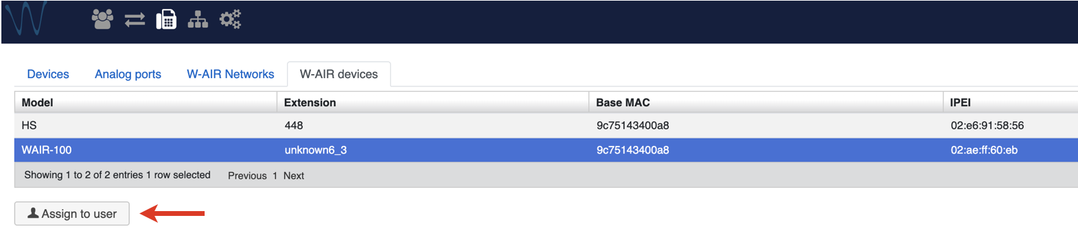
Go to WMS -> Devices -> W-AIR devices
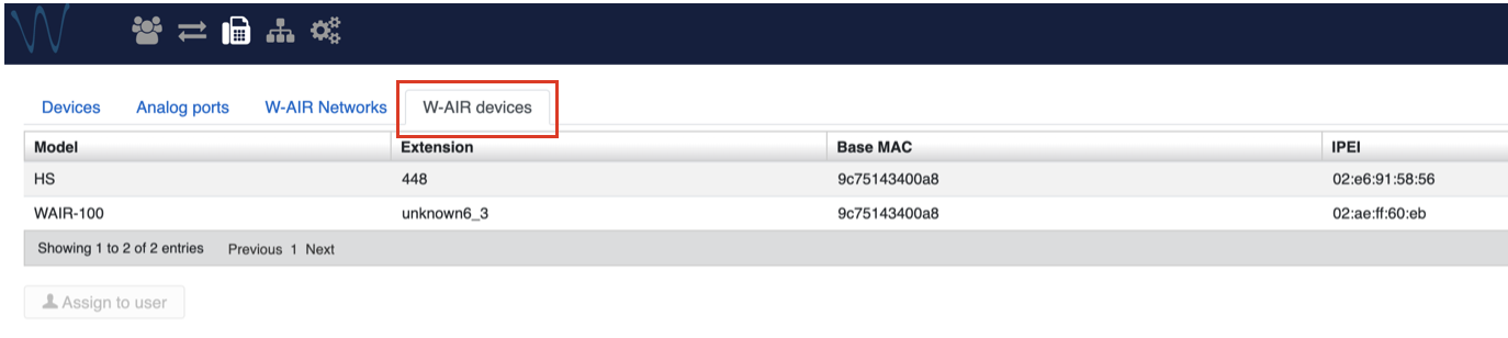
Choose the handset and click Assign to user
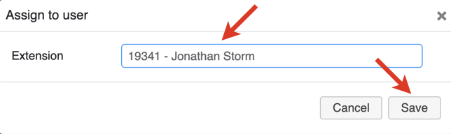
Enter user extension and click Save
Note: To figure out which handset received the assigned extension, you can dial this extension and see which handset rings.
To assign W-AIR handset to a different user:
- Choose the handset on the W-AIR devices tab -> click Assign to user
- Enter a different extension and click Save
To deassign a W-AIR handset:
- Choose the handset -> click Assign to user
Select “unknown” in the Extension field
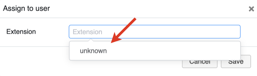
- Click Save
Step 5. Set up Repeaters
In a multi-cell installation, up to 3 repeaters per base are supported:
- Up to 50 bases: 3 repeaters
- 50-125 bases: 1 repeater
- More than 125 bases: no repeater
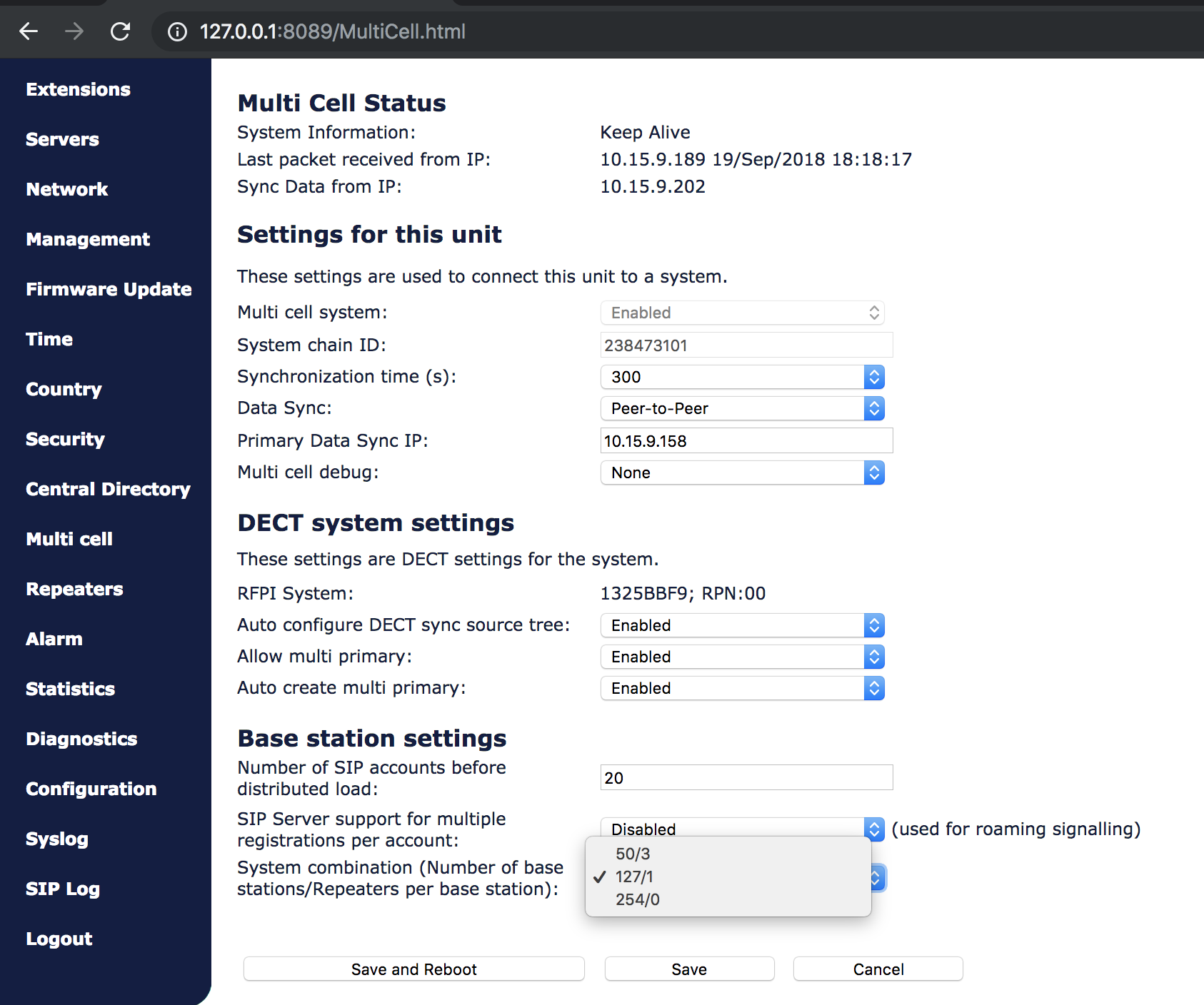
Depending on the number of Bases (in case of multi-cell installation), you should specify the number of Repeaters on the web interface of the Base station (under Base station settings):
Proceed as follows:
- Find the IP of the base station that you want to repeat (on the WMS devices list)
- Access the base station's web interface, enter a username “admin” and a password that you can find in the WMS Devices menu in the “Password” field of the given base station
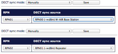
- Select Repeaters in the menu and click on Add Repeater
- Select Manually from the drop-down menu if it is present, then choose the Station ID (DECT sync source) where you want to connect the Repeater and confirm by pressing the Save button
- Reboot the Base station (go to Management menu and click Save and reboot). After the system reboots, go back to the base station’s interface
- Select Repeaters in the menu
- Select a Repeater(s) you want to add to the chain and click on Register Repeater(s)
- Now you have 5 minutes to turn on the Repeater(s)
- LED of the Repeater should turn solid green in several seconds, if it fails (solid RED), please repeat the steps after the reboot of the base station
Notes:
- If you have any problems with registering Repeater(s), reset it by pressing the Reset button on the back side for more than 2 seconds (LED turns solid RED and then GREEN with a double pulsation)
- Start the registration procedure again by following the last three points above
- Repeater should be placed on a distance not less than 10 meters from its Base station
- For a good conversation and a correct handover between Bases and their Repeaters the dBm value should be between -75 and 0
W-AIR Network auto roaming feature
Features:
- up to 250 offices/ base stations – 1000 handsets/ users in one DECT network
- redundant – all offices base stations are autonomous
- roaming – users can roam over all base stations/ offices
- user sign-on/ hot desking
- centralized phonebook with presence
Thanks to WMS Network up to 500 PBXs – HW, VM or Cloud PBXs – connect together and create a peer to peer Telephony network which is secure, synchronized. The base stations of the DECT network can be connected to any one of the PBX (with a secondary one as failover) and work even in case internet is not available. The handsets information is shared via IP service over the DECT gateways network.
Users can roam all over the base stations preserving their internal number. When a user moves between from office to another, location is automatically updated and the personal settings (forwards, call management rules) are retrieved. Users do not need the help of an administrator to start using an handset, the sign-on require to enter via IVR the phone number and personal pin code. It is easy to share the phone between many users as sign-on / sign-off operators require just a few seconds.
Requirements:
- layer 3 VPN over all sites
- support for UDP fragmentation (since MTU of packets is over 1500 bytes)
- base stations must be able to reach each other via IP
How-to:
- Enter the local IP address of the Primary Base Station into the field “Primary Base IP” (Devices -> W-AIR Networks -> "Edit" Network)
- Connect all the base stations and add them to the WMS Network Server PBX
- Set as DNS server for each base station (in Devices -> Edit device) the PBX to which the base station must be connected
- Set as DNS name “auto.wildixin.com” in the field “SIP Proxy” (Devices -> W-AIR Networks -> Edit Network) to have all phones connected to the correct PBX (this is possible thanks to point 3)
Multicell network debug options
Multicell network overview
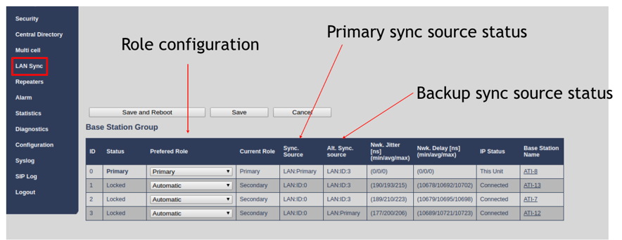
After you have enabled the option "Sync Plus via Ethernet" (described in the previous chapter, Step 2), you can view the multicell network configuration on the base station's web interface, menu LAN Sync:
Debug options
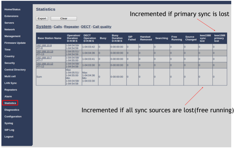
On the base station's interface, menu Statistics, pay attention to the columns "ieee1588 sync lost" and "ieee1588 primary sync lost". These values should be equal to 0:
You can check the Delay and the Jitter on the base station's interface, menu LAN Sync:
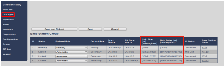
Expected jitter levels for different types of switches:
- Fix parts connected to Aruba HP switch will have expected jitter < 300ns
- Fix parts connected via 3 layer switch will have expected jitter < 500ns
- Fix parts connected via 7 layers switch will have expected jitter < 2000ns
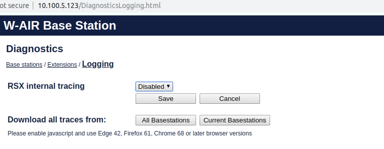
Diagnostics Logging
The option is available starting from firmware v. 0450b13.
The Logging option allows collecting system diagnostics information into a zip file and download it.
- Go to Diagnostics -> Logging
- Enable RSX internal tracing and click Save
- After diagnostics information is collected, you can download traces
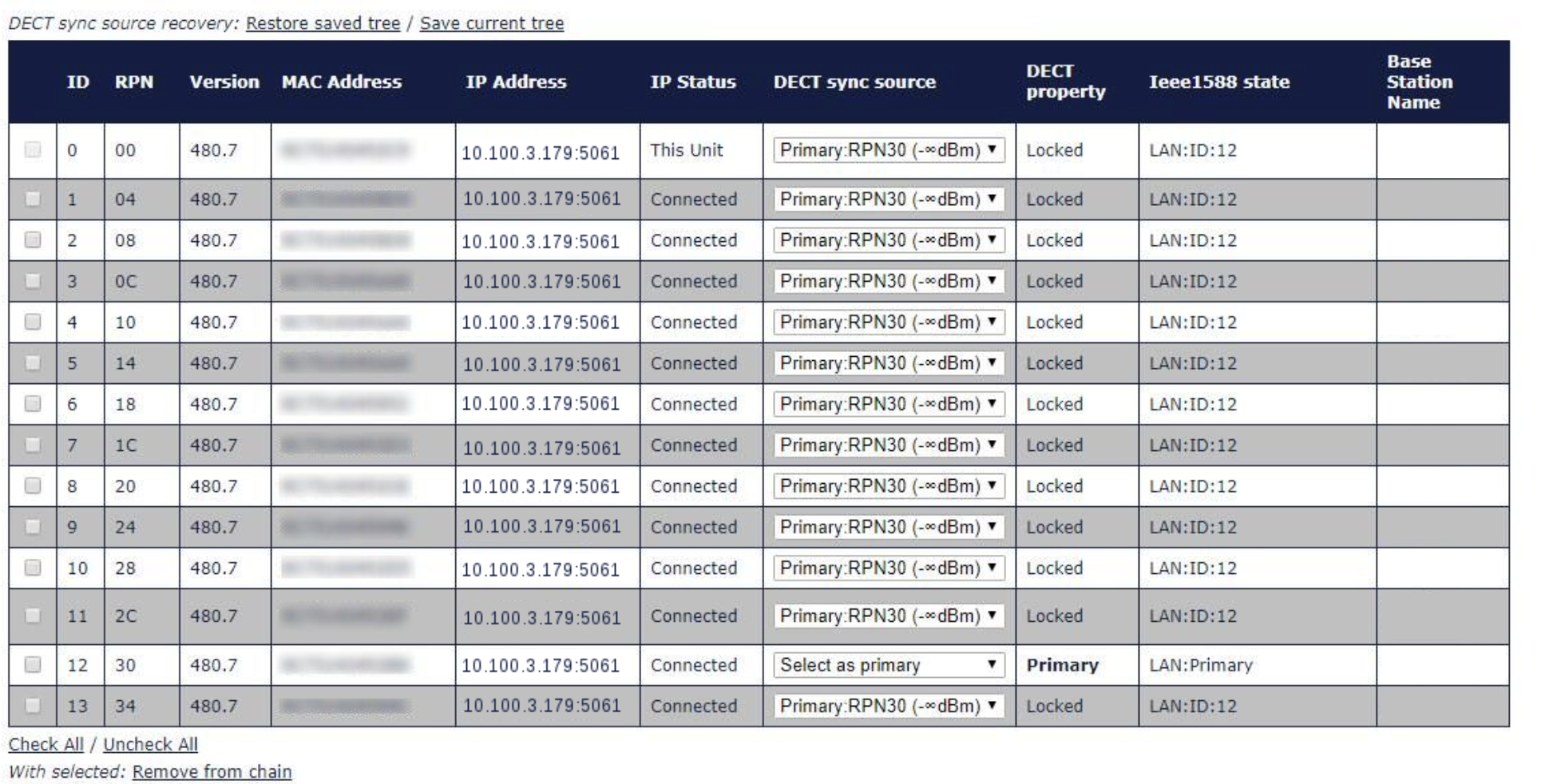
Radio Coverage
When checking the Radio Coverage on the web interface of the Base station -> menu Multi Cell, pay attention that the coverage values of every connected base in DECT sync source column are infinite by design.
Statistics
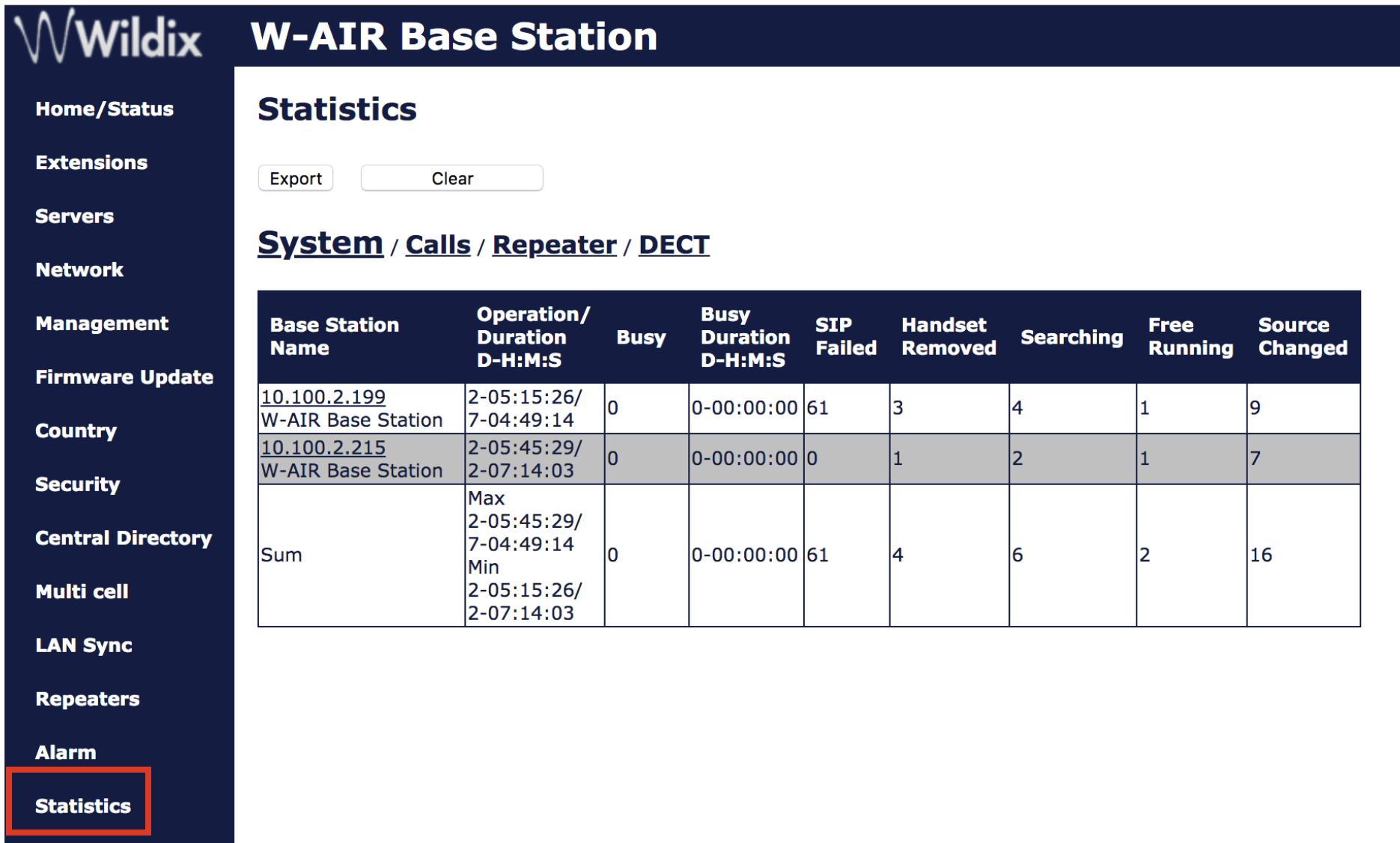
Menu Statistics, accessible via base station web interface, offers access to four administrative menus, allowing the system administrator to monitor:
- System
- Calls
- Repeater
- DECT data
- Call quality.
System data
PARAMETERS | DESCRIPTION |
BASE STATION NAME | Base IP address and base station name from management settings |
OPERATION/DURATION D-H:M:S | Operation is operation time for the base since last reboot. Duration is the operation time for the base since last reset of statistics, or firmware upgrade. |
BUSY | Busy Count is the number of times the base has been busy. |
BUSY DURATION D-H:M:S | Busy duration is the total time a base has been busy for speech (8 or more calls active). |
SIP FAILED | Failed SIP registrations count the number of times a SIP registration has failed |
HANDSET REMOVED | Handset removed count is the number of times a handset has been marked as removed |
SEARCHING | Base searching is the number of times a base has been searching for its sync source |
FREE RUNNING | Base free running is the number of times a base has been free running |
DECT SOURCE CHANGED | Number of time a base has changed sync source |
Free running explained
Free running is NOT an error state, but is a simple trigger state, indicating that some changes have to be made to ensure continuous DECT synchronization.
Free running tells the application that the base has not received any sync data from its sync source base station during the last 10 seconds.
The reasons for this behavior can be the following:
- Two bases are using the same DECT slot and therefore cannot see each other.
- Too many simultaneous calls.
- A sudden change of environment (e.g. closing a fire door)/.
- Distortion of DECT frequency (around 1.8MHz) either by other DECT systems or other equipment.
When the Free running state is trigged the following actions are recommended:
- Move DECT slot to avoid using the same DECT slot as another base as its synchronization source base state.
- Use information from other base stations, to check how they are seeing this base station in the DECT air.
Free running activates several recovery mechanisms: the state changes to Assisted lock. The state Assisted lock can remain stable for a long time and normally changes to state Locked again. The state Free Running can also change back to state Locked again.
If the base is in state Free running and the synchronization source base station cannot be seen and no data is available for the assisted lock mechanism, the base station will change to a new state after 2 minutes:
- If the base station does NOT have any active calls, the base will change to state Searching.
- If the base station has an active call, this base will change to state Sync lost. After the call is released, the state will change to state Searching.
Call data
PARAMETERS | DESCRIPTION |
BASE STATION NAME | Base IP address and base station name from management settings |
OPERATION TIME/DURATION | Total operation time for the base since last reboot or reset Duration is the time from data was cleared or system has been firmware upgraded. |
COUNT | Counts number of calls on a base. |
DROPPED | Dropped calls are the number of active calls that was dropped. E.g. if a user has an active call and walks out of range, the calls will be counted as a dropped call. An entry is stored in the syslog when a call is dropped. |
NO RESPONSE | No response calls are the number of calls that have no response, e.g. if an external user tries to make a call to a handset that is out of range the call is counted as no response. An entry is stored in the syslog when a call is no response. |
DURATION | Call duration is total time that calls are active on the base. |
ACTIVE | Active call shows how many active calls that are active on the base (Not active DECT calls, but active calls). On one base there can be up to 30 active calls. |
MAX ACTIVE | Maximum active calls are the maximum number of calls that has been active at the same time. |
CODECS | Logging and count of used codec types on each call. |
HANDOVER ATTEMPT SUCCESS | Counts the number of successful handovers. |
HANDOVER ATTEMPT FAILED | Counts the number of failed handovers. |
AUDIO NOT DETECTED | Counts the number of times where audio connection was not established. |
Repeater data
PARAMETERS | DESCRIPTION |
IDX/NAME | Base IP address and base station name from management settings |
OPERATION D-H:M:S | Total operation time for the repeater since last reboot or reset Duration is the time from data was cleared or system has been firmware upgraded. |
BUSY | Busy Count is the number of times the repeater has been busy. |
BUSY DURATION D-H:M:S | Busy duration is the total time a repeater has been busy for speech (5 or more calls active). |
MAX ACTIVE | Maximum active calls are the maximum number of calls that has been active at the same time. |
SEARCHING | Repeater searching is the number of times a repeater has been searching for it’s sync source |
RECOVERY | In case the sync source is not present anymore the repeater will go into lock on another base or repeater and show recovery mode |
DECT SOURCE CHANGED | Number of time a repeater has changed sync source |
WIDE BAND | Number of wideband calls on repeaters |
NARROW BAND | Number of narrow band calls on repeaters |
DECT data
PARAMETERS | DESCRIPTION |
FREQUENCY | Number of the DECT slot frequency |
SLOTX | Number of connections that have been active on each frequency |
Call Features
DND, Call forwarding, Paging, Call intrusion, Intercom
All the Call Features can be set up in WMS or Wildix Collaborations in User Settings, or otherwise, directly from the handset, by dialing the Feature Codes of the system.
Consult the guide Feature Codes and Pre answer Services - Admin Guide.
Ring tones
Ring tones set in Collaboration are not applied to W-AIR handsets. You can set ring tones via Dialplan "Set" application.
Consult Dialplan applications Admin Guide.
Call transfer, hold, call swap, conference call
These operations can be performed directly from W-AIR handset, consult the guide W-AIR DECT Handset for details.
W-AIR Handsets support only 2 calls/ channels, this means, when you have one active call and one call on hold, you can only perform a transfer of the active call to the party which is on hold, or vice versa. You cannot transfer a call to some third party, because no more channel can be opened.
If you need to transfer a call to some third party when you have one active call and one call on hold, you can use in-call Feature codes (since it doesn't require opening a new channel): #8 for attended transfer and #9 for blind transfer. Consult Feature Codes and Pre answer Services Guide for detailed information.
Upgrade Procedure of W-AIR system
W-AIR Upgrade logic in WMS 5.03.
Starting from WMS version 5.03.20210709.3, W-AIR System is upgraded according to the following policies:
- there is 4 hours timeout for W-AIR upgrade
- if all base stations are upgraded earlier than the timeout is reached, handsets and headsets upgrade is started immediately
- after 4 hours if some base stations are still not upgraded, devices will be upgraded in any way
FW upgrade of Base Stations
When there is the new FW available, the notification "Firmware available" appears in WMS -> Devices.
To upgrade the FW, select one or multiple base stations, and click Configure/Sync. Wait for several minutes, during the FW upgrade, devices are rebooted. As soon as the upgrade procedure is finished, the new FW version appears in the Devices menu of the WMS, the base stations are no longer marked with the blue color.
FW upgrade of Repeaters and Handsets
After the upgrade of the base stations, Repeaters and Handsets connected to the system download the new FW automatically. You can monitor the process of the FW upgrade from the base station’s web interface.
Repeaters
- Repeaters must be connected to be able to perform the upgrade procedure
- Do not turn off or reboot repeaters manually during the upgrade: they restart automatically
Go to the Base Station interface, menu Repeaters: during the reboot you can see the progress of the upgrade of the repeaters in the field “FWU Progress”. As soon as it’s finished, the “FWU Progress” displays “Complete”.
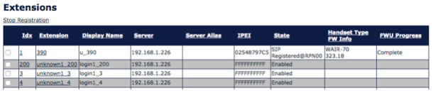
Handsets
New FW is downloaded automatically after the Base Stations have been upgraded. To complete the FW upgrade procedure of the handsets, the handsets must be placed into the charger
During the procedure you can see the status of the upgrade of the phones, the procedure takes about 30 minutes. Go to the Base Station interface, menu Extensions (only for Base Station: Go to tab “Handset” of menu Extensions ): during the reboot you can see the progress of the upgrade in the field “FWU Progress”. As soon as it’s finished, the “FWU Progress” displays “Complete”.
Alarms setting
Types of alarms
Alarm Button
This alarm is triggered by long-pressing (3 seconds) the red button on top of the handset.
Pull Cord Alarm
The Pull Cord alarm can be triggered by pulling a cord containing a magnet from the pull cord hole on the right side of the handset.
Running Alarm
To trigger the Running Alarm the handset needs to be shaken up and down for several seconds.
Man Down Alarm
The Man Down alarm is triggered if the handset remains in the position with an angle over 60 degrees with respect to the horizontal. The time for the handset to be still before the alarm is triggered can be set on base station web interface (read the next chapter 7.3. Set up emergency profiles)
No Movement Alarm
To trigger the No Movement alarm the handset needs to be in no movement. The timeout after which No Movement alarm is triggered is set on the base station web interface.
Set up emergency profiles
Go to the menu Alarms. In this menu eight different alarm profiles can be configured. The parameters that can be configured are:
- Profile Alias: A user friendly name to help identify the different profiles when selecting which one to enable for individual handsets
- Alarm Type: The type of event that triggers an alarm. The options are: Disabled, Man Down, No Movement, Running, Pull Cord, Alarm Button
- Alarm Signal: Call. The alarm is made as an outgoing call to the emergency number preconfigured for the extension
- Stop Alarm from Handset: Enable/ Disable. The possibility to cancel an alarm from the handset
- Trigger Delay: The timeout before the phone starts showing pre-alarm warning. If set to 0, the alarm is sent immediately (max. value is 255 sec.)
For Man Down alarm, add the default delay of 6 seconds which is the time needed for the alarm detection (e.g. if set to “0”, alarm is triggered after 6 sec, if set to “30”, alarm is triggered after 36 sec.)
- Stop Pre-Alarm from Handset: Enable/Disable the possibility to cancel the pre-alarm from the handset
- Pre-Alarm Delay: The timeout during which the pre-alarm warning is displayed until the actual alarm is sent (max. value is 255 sec.)
- Howling: Enable/Disable the howling of the handset when the alarm is triggered

After you have defined the Emergency profiles, click Save to apply.
Assign emergency profile to handsets
- Go to the menu Extensions
Click on the field “Idx” or “Extension” of the handset:
The following window is displayed, allowing you to set up emergency settings:
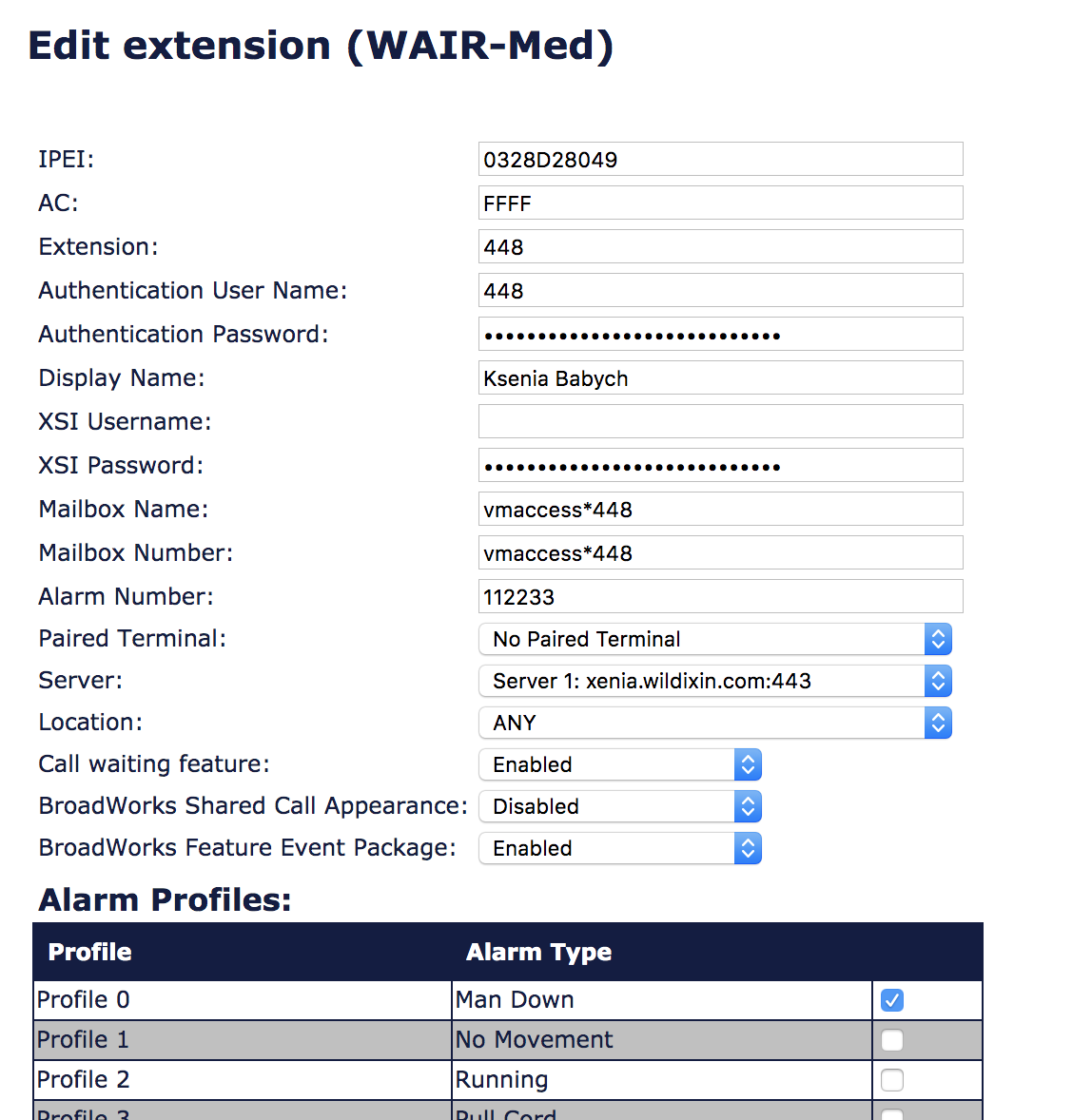
Modify the parameter “Alarm Number”: enter the number to be called when the alarm is triggered from the handset:
You can enter an extension number that must be called or customize the service by modifying the Dialplan in the WMS and to add the “Alarm Number” as a Called number into a Dialplan procedure.
Tick off the Profiles that you wish to enable for this handset
Click Save at the bottom of the page
Go to Management menu and click Save and reboot to reboot the base station and apply the new parameters
Alarms localization
Read the guide How to get location of W-AIR Base Station in case of emergency alarm. The guide explains how to get the location of the nearest W-AIR Base Station in W-AIR Network in case of an emergency alarm triggered on the W-AIR Handset.