WSG24POE - Admin Guide - English
The line of Wildix network switches WSGxxPOE is going EOL after the current stock is over.
You can check the availability of items remaining in stock on WMP.
This manual explains how to log in and to configure WSG24POE via administrator web interface of the switch.
Version created: June 2016
Version updated: June 2018
Permalink: https://wildix.atlassian.net/wiki/x/jQrOAQ
On this page:
Initial connection
Turn on the switch
Before powering on the switch, make sure the voltage is correct. The power supply socket is situated on the back panel of the switch.
Plug the power supply into the switch: the power indicator on the front panel must turn on.
LED indicators and ports description
Front panel:
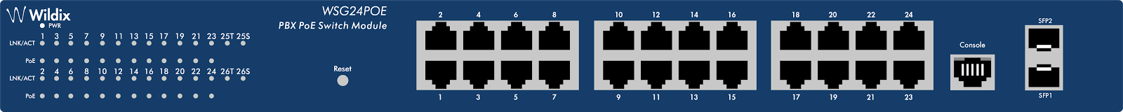
Ports description:
10/100/1000Mbps RJ45 ports (1-24): connect devices with 10 / 100 / 1000Mbps bandwidth.
SFP ports (SFP1, SFP2): install SFP module and connect devices with 1000Mbps bandwidth.
Console port (Console): connect a serial port of PC / terminal for monitoring and configuring the Switch.
Reset button (Reset): (device is connected to power supply) press and hold the button for about 5 sec.
LEDs description:
LED | Color | Status | Description |
PWR | Green | ON | Power is supplied |
OFF | No power | ||
Link / Act / Speed (1-24) | Orange (10/100Mbps) | ON | A valid link is established |
OFF | No link is established | ||
Green (1000Mbps) | Blinking | Data packets are received or transmitted | |
Link / Act / Speed (SFP1,2) | Green | ON | A valid link is established |
OFF | No link is established | ||
Blinking | Data packets are received or transmitted | ||
PoE (1-24) | Yellow | ON | A PoE PD (Powered Device) is connected to the port |
OFF | No PD is connected to the port | ||
Blinking | The PoE power circuit may be in short or the power current may be overloaded. |
Access web interface
The default settings of the Switch:
Default IP address: 192.168.2.1
Default user name: admin
Default password: admin
(PC must be in the same network as the switch: 192.168.2.xxx)
Connection of devices
Connect devices to the ports of the Switch using a network cable (check the datasheet for more information). 1-24 ports have power supply function (see the datasheet for the max power output)
How to configure Voice and Data Vlans
Firmware version: V103SP6D180529 and Firmware version: V103SP7D230713
Upgrade the switch
- Download the firmware from Google Drive: https://drive.google.com/drive/folders/1KSkyO5Plf8DckvhH3dENsJ8MDDJ8uxcI or the latest version of firmware https://drive.google.com/file/d/1jiA3Md2Wob2wBB7vltMWPujFu5plR_er/view?usp=sharing
Access the web interface of the switch, Menu System-> System Update to upgrade the switch After the upgrade to this version the switch must be reset: press and hold the Reset button for about 5 sec.
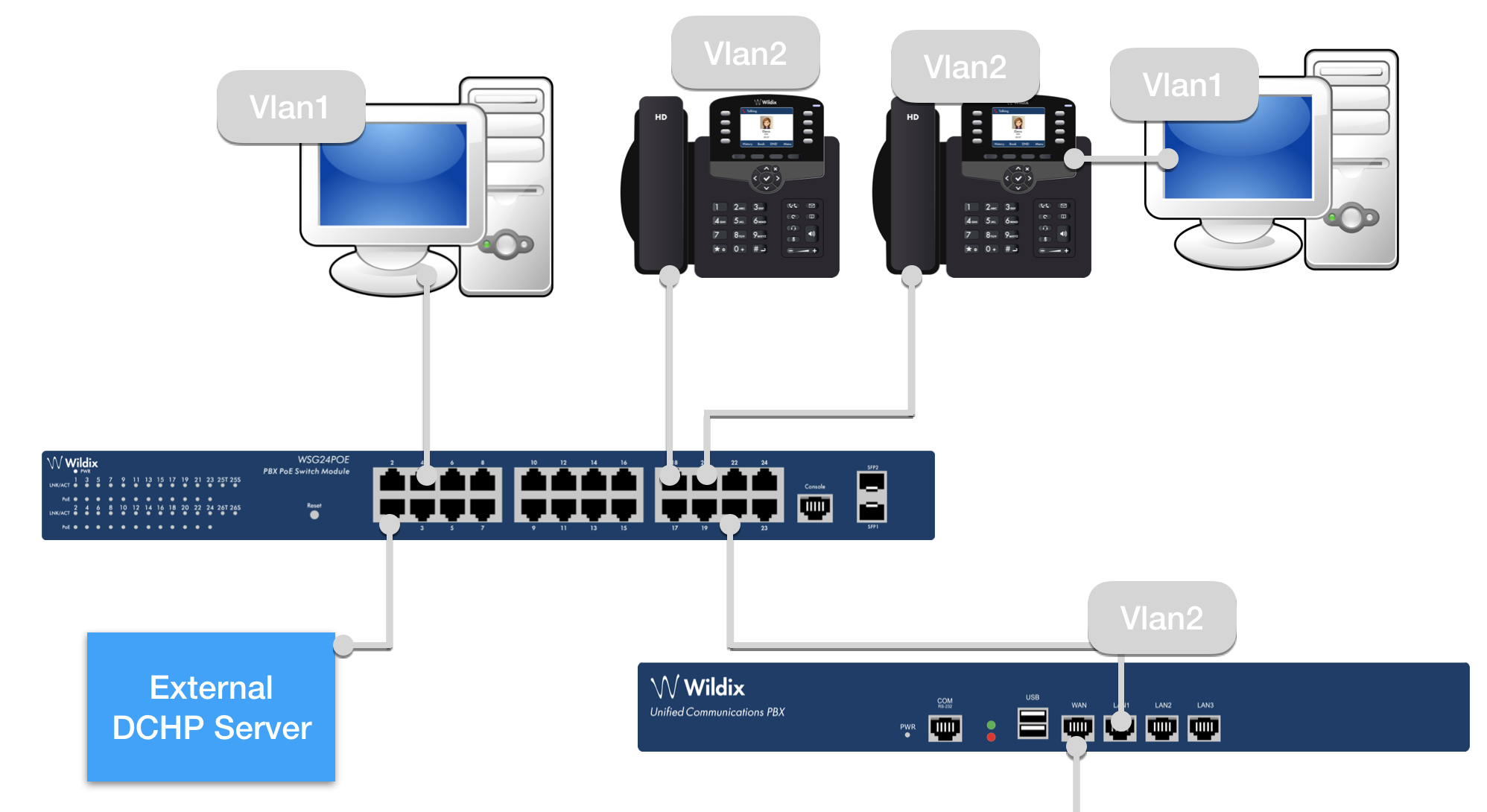
Connection Scenario
- Phones and PCs are connected to the switch
- LAN port of the PBX is connected to the switch (WAN port of the PBX is connected to WAN switch, for external access)
- Phones and Wildix devices as well as LAN PBX port get the IP from the Switch, in our example, from the pool 192.168.1/24
- PCs get IP from the external DHCP server, reachable by the switch via port 1, in our example, 192.168.133.91
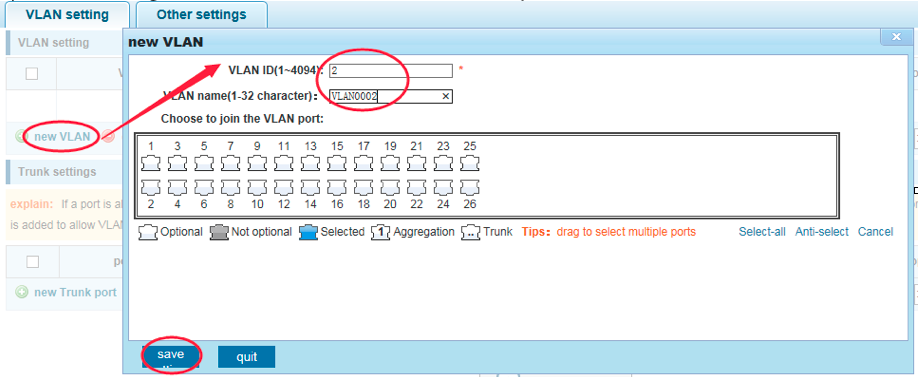
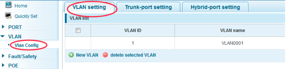
Create new VLAN ID
- Go to VLAN Management → Vlan Config → Vlan Settings
- You have Vlan 1 created by default in this menu
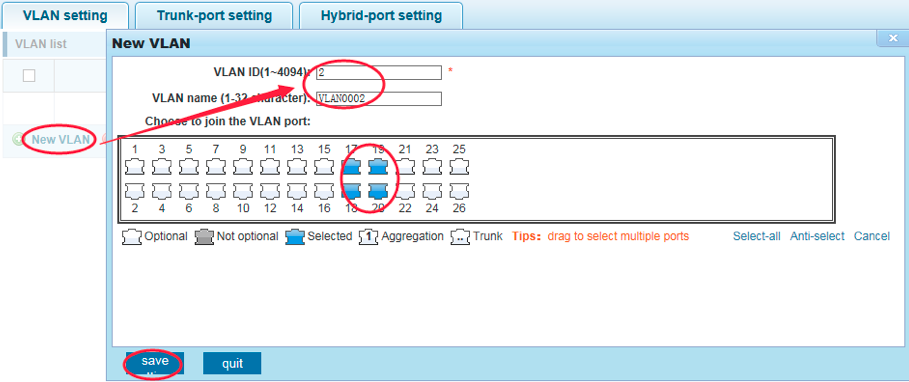
- Create Vlan 2 and enable it for all the ports excluding the port that you used to connect the switch to PC
Create Voice VLAN
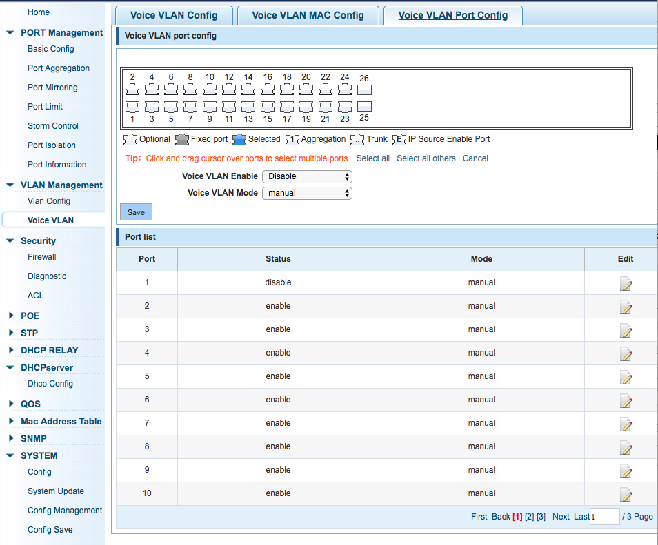
- Go to VLAN Management → Voice Vlan → Voice VLAN Config
- Set the flag for Voice VLAN Enable and set Voice VLAN ID
- Go to the tab Voice VLAN Port Config and enable VLAN on ports all the ports excluding the one you used to connect your PC
- Disable VLAN on the port on which the external DCHP server is supposed to be reachable (port 1 in our example)

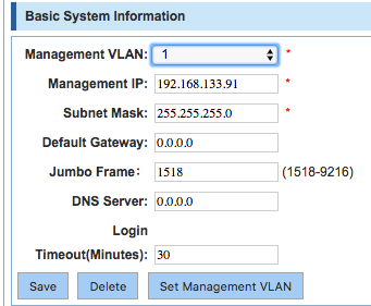
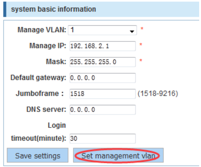
Configure the Management VLAN
- Go to System → Config
- Make sure the switch time settings are correct in System Time section
- The Management Vlan is already configured on Vlan1 by default (192.168.2.1)
- Press Set Management VLAN
- Set:
- Management VLAN: 2 (Voice VLAN ID)
- Management IP: 192.168.100.1 (Management IP of the switch on Vlan2)
- Subnet mask: 255.255.255.0
- Default gateway: 0.0.0.0
- Press Save

Note: The IP pool of DHCP server running on Vlan2 must be in the same network as the Management IP on Vlan2 (in our example, 192.168.100.0/24), this is why we change the Management IP on Vlan1.
In our example we have also changed Management VLAN1:
Note: after changing Management VLAN 1, you will lose access to the switch and you will have to reconnect using the new IP.
Set Hybrid Ports
- Go to VLAN Management → Vlan Config → Hybrid Port Settings
- Remove VLAN TAG: 1-2 for ports 2-26:

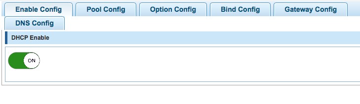
Enable DHCP Server
- Go to DHCPServer → Dhcp Config and enable the option (move the switch in ON position)
- Go to the tab Pool Config to configure the pool of IP addresses released by DHCP server
In our example the Pool ID 2 is associated to Vlan 2 and is used to assign IP addresses from the following range: 192.168.100.1 - 192.168.100.255 (external DHCP server for PC will be connected to port 1):

External DHCP
To disable Voice VLANs and internal DHCP server, and to enable only the external DHCP to release IP addresses, you have to disable Voice Vlan in Vlan Management → Voice VLAN
To enable external DHCP to release IP addresses to the PC network, we have to enable the Trusted IP port, to which the DHCP server is connected.
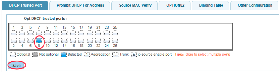
Go to Security → Firewall → Dhcp Trusted Port to add the trusted port:

To enable external DHCP server to release IP addresses to the PC network, we have to enable the snooping Vlan on Vlan1, where the DCHP server is connected.
Go to the tab Other configuration → Dhcp Snooping Vlan and add the Vlan1:

Results
Going back to VLAN Management → Vlan Config menu, you should see the following configuration:

- Wildix Phones connected to any ports of the Switch receive IP address from Vlan 2 pool
- PCs connected to Switch ports receive IP from Vlan 1 pool
- Wildix Phones connected to any ports and PCs connected to PC port of the phone: phone gets IP on Vlan 2, PC gets IP on Vlan 1
Menu description and configuration
Home
The home page displays the following information:
Configuration menu (at the bottom)
Software and Hardware Versions (on the top)
Status of ports
Quickly Set
Create a VLAN
Add port in VLAN
Set the basic information and change the switch login password
Configuration example
Create VLAN:
Add port in VLAN:
Set the basic information:

Change the switch login password (use the IP address set up on the previous step to log in):
PORT Management
Submenus:
Basic Config
Port Aggregation
Port Mirroring
Port Limit
Storm Control
Port Isolation
Port Information
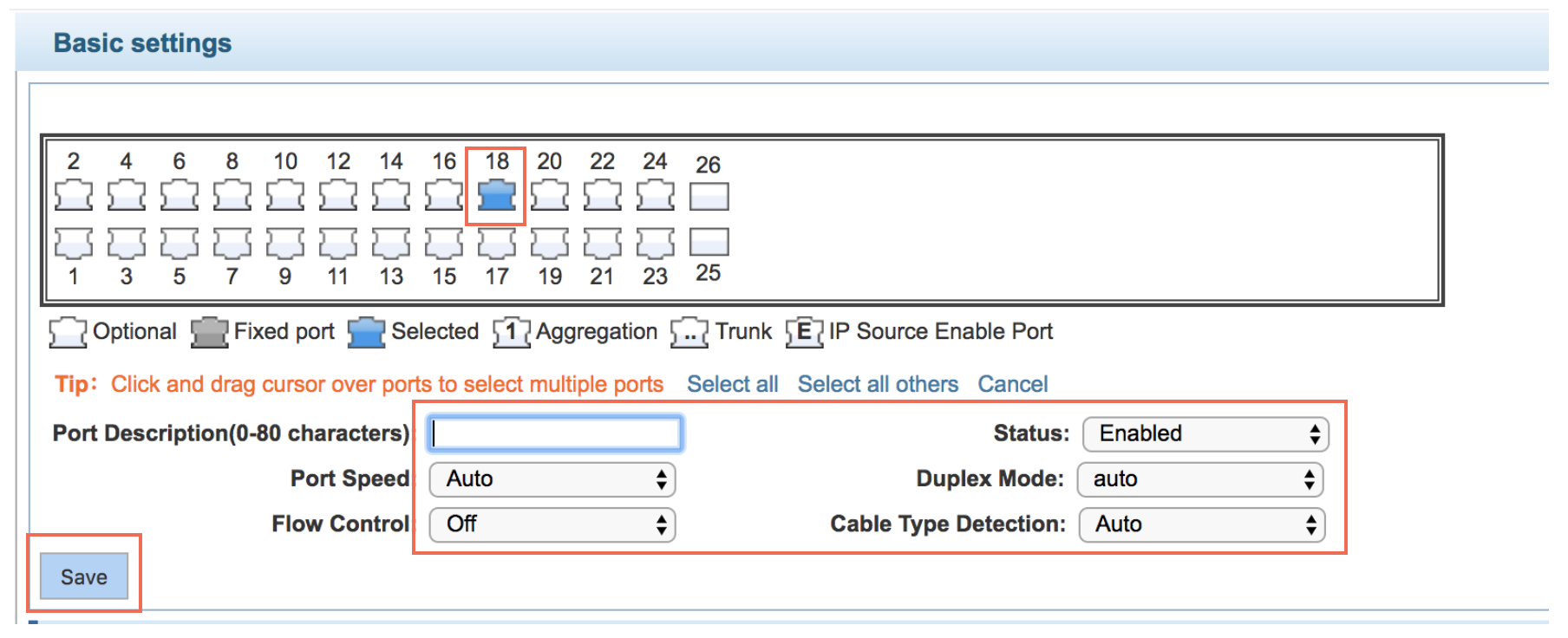
Basic Config
Set up:
Port Speed
Status
Duplex Mode
Flow Control
Cross Type Detection
Configuration example:
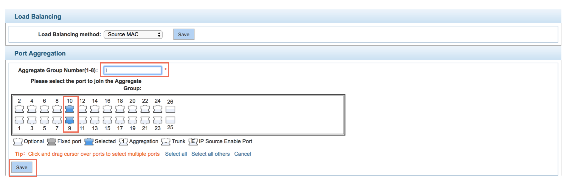
Port Aggregation
- Select Load Balancing method
- Expand the port bandwidth or achieve the bandwidth of the redundancy backup
Configuration example:
Set the ports 9-10 for aggregation of port 1, the aggregation port 1 can build switch links if connected to another switch aggregation port 1:
Port Mirroring
Open port mirror feature
All packets on the source port are copied and forwarded to the destination port, destination port is usually connected to a packet analyzer to analyze the source port, multiple ports can be mirrored to a destination port.
Configuration example
Set a mirror group for port 3 regulatory port 4, 5, 6 on and out flow conditions:

Port Limit
Set up:
Input Speed Limit
Output Speed Limit
1Mbit/s=1000Kbit/s=1000/8KB/s=125KB/s (The theoretical rate of 1M bandwidth is 125KB/s)
Configuration example
Set up on port 5 input rate - to 6400KB/s, the output rate - to 3200KB/s

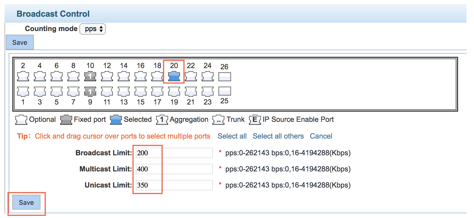
Storm Control
Set suppression limits
Configuration example
Set up on port 20 broadcast limit is set to 200pps, the multicast limit - to 400pps, the unicast limit - to 350pps.
Port Isolation
Isolate port from one or multiple destination ports
All packets on the source port are not forwarded from the isolated port, and one port can be separated from multiple destination ports.
Ports that have been added to the aggregate port aren't also capable of being a destination port and source port. Destination port and source port cannot be the same.
Configuration example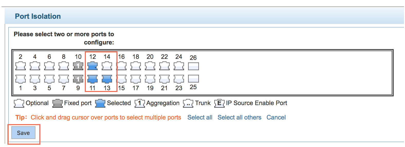
VLAN Management
Manage:
- Vlan Config
- Voice VLAN
Vlan Config
Manage:
VLAN Settings
Access Port Settings
Trunk Port Setting
Hybrid Port Settings
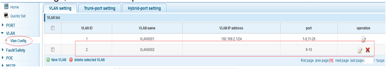
VLAN settings
Create VLANs and set the port to the VLAN (port default state for the access mode)
Default VLAN cannot be deleted. Add ports to access port, port access mode can only be a member of the VLAN.
Configuration example
Create VLAN2:
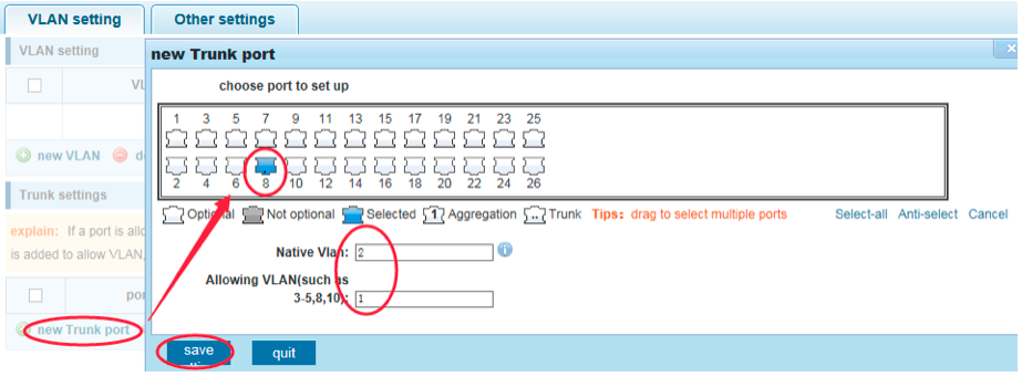
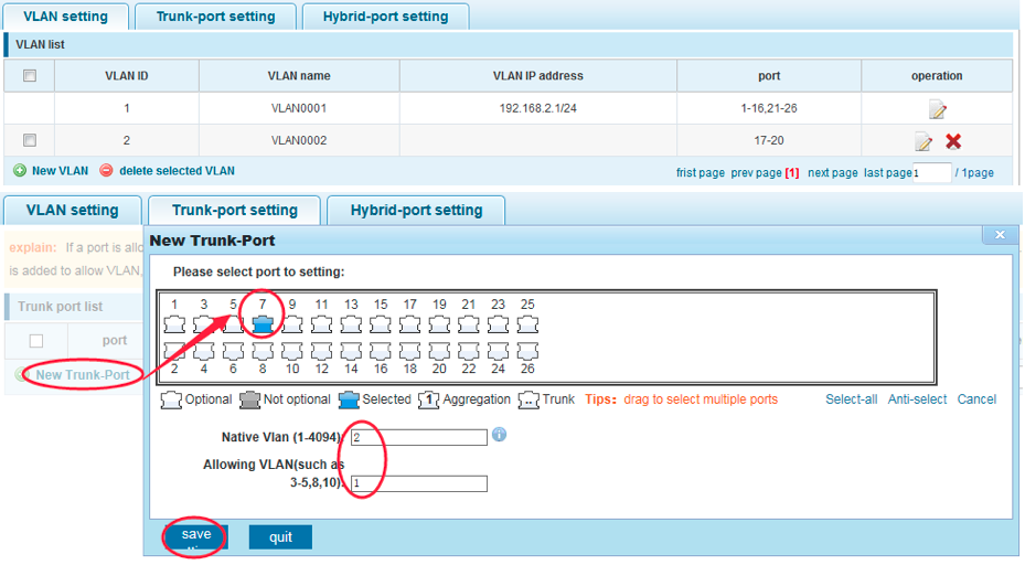
Trunk-port setting
Set port to Trunk port
Configuration example
PVID=VLAN2.
PC1: 192.168.2.122, port 18, access VLAN2.
PC2: 192.168.2.123, port 7, Trunk allowed VLAN 1-2.
PC3: 192.168.2.124, port 6, access VLAN1 (The default port belongs to VLAN1).
Can let the PC2 PING PC1, cannot PING PC3.
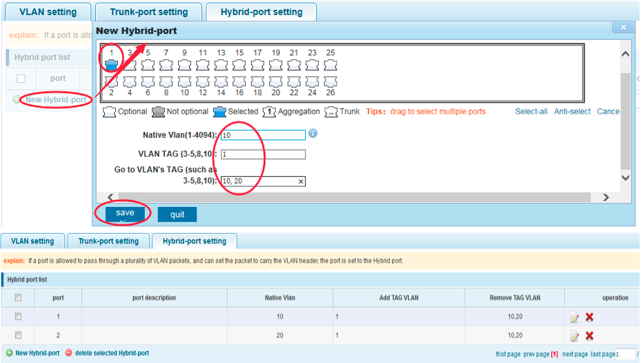
Hybrid-port setting
Allows to set VLAN tags
Hybrid port receives a packet and checks if there is VLAN tag, and based on it forwards the packet or discards it.
Configuration example
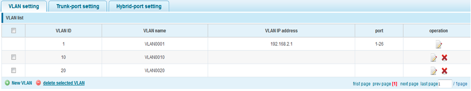
Create VLANs 10, 20, VLAN sets the Native VLAN port 1 to 10, to tag VLAN for 10, 20, sets the Native VLAN port 2 to 20, to tag VLAN for 10, 20.
Fault / Safety
Anti Attack
Channel Detection
ACL
Anti Attack
Anti DHCP Attack
Anti DOS
IP Source Guard
Anti Three Bind
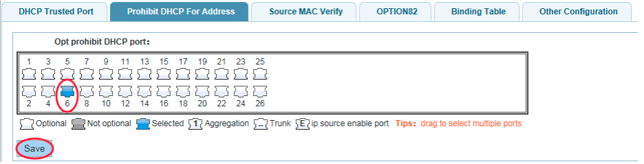
Anti DHCP Attack
Allows you to select port as a trusted port
Configuration example
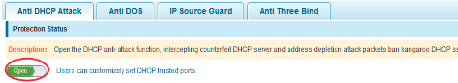

Set trusted port and prohibited port:
Verify source MAC address and set server IP address:
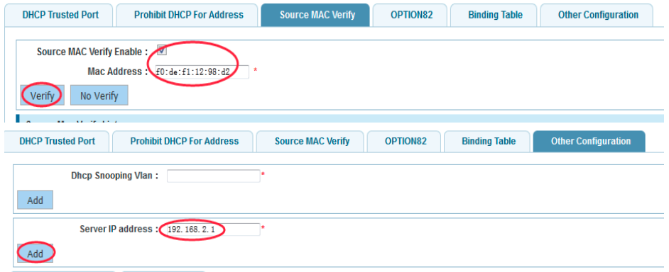
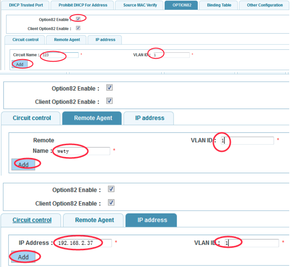
Set option82 information:
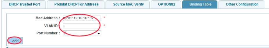
Set port 7 for binding:
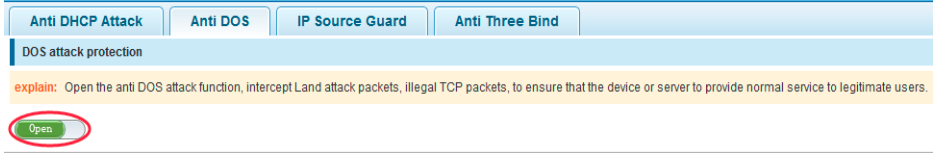
Anti DOS
Enable anti DOS attack function to intercept attack packets and illegal TCP packets
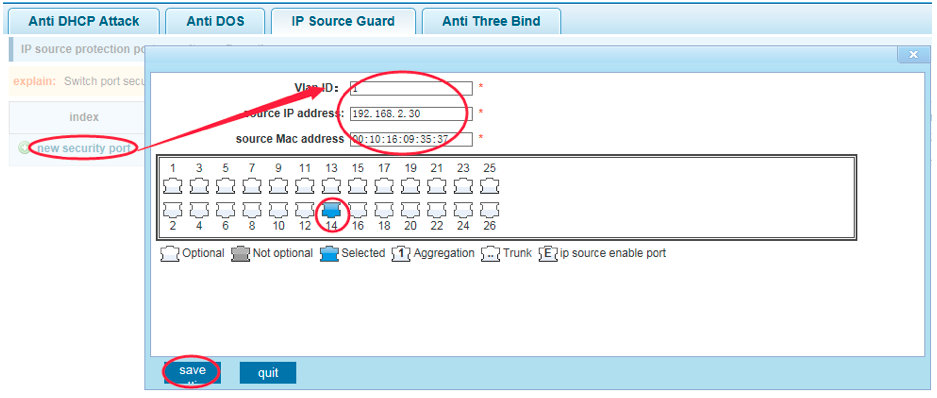
IP Source Guard
Enable the packet filter control to prevent illegal messages through the port and limit illegal use of network resources
Configuration example
Set port 14 as a secure port
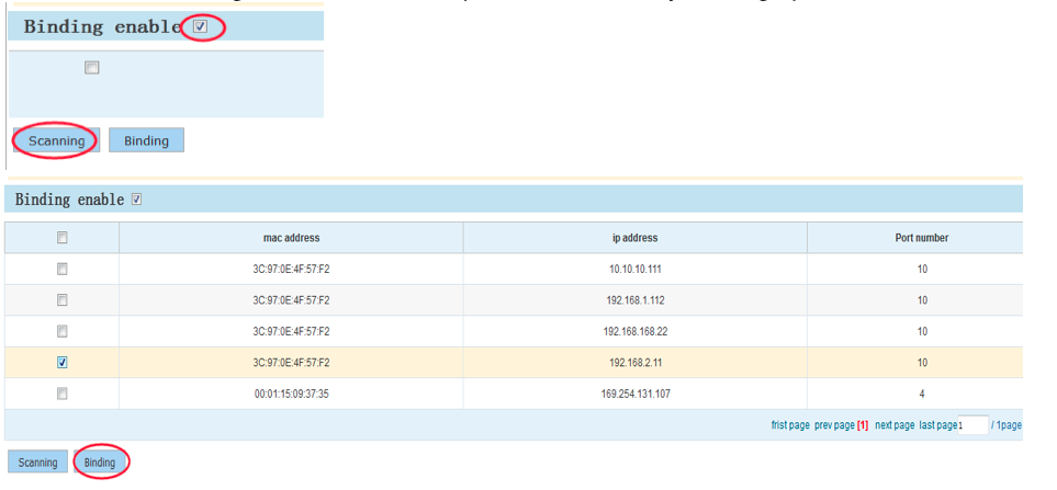
Anti Three Bind
Allows to bind IP address and MAC address
Configuration example
Channel Detection
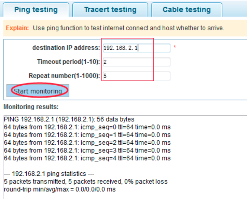
Pint testing
Ping a host
Configuration example
Ping IP address of PC connected to the switch
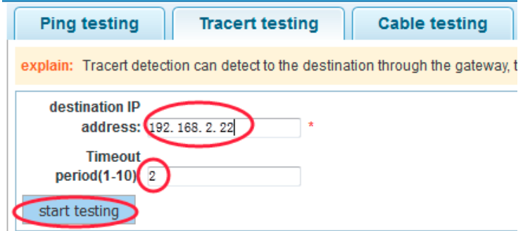
Tracert testing
Perform an interface traceroute test
Configuration example
Check an IP address of PC connected to the switch
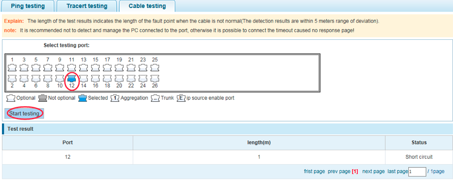
Cable testing
Check connection status of device
Configuration example
ACL
Set up ACL rules and their priority
Configuration example
Set the timetable for your ACL rule:

Create ACL rules:
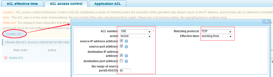

Apply ACL to ports:

PoE
PoE Config
PoE Port Config
PoE Config
To receive trap notices, SNMP must be open and the Trap must be set to the target host.
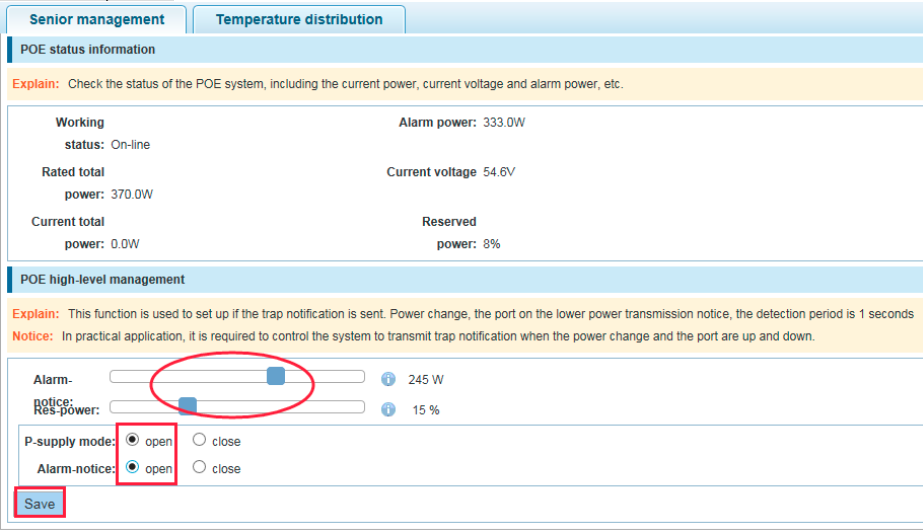
Senior management
View PoE state information
Change the configuration
Configuration example
Alarm power set to 245W, reserved power to 15%, open the supply mode and the alarm power.
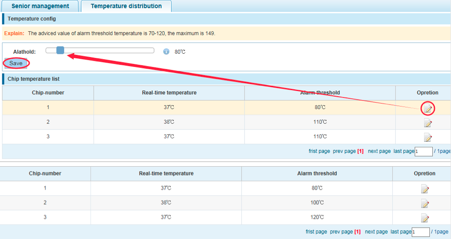
Temperature distribution
Set up the alarm threshold
Configuration example
1 warning threshold is set to 80 chip, chip 2 warning threshold is set to 100, chip 3 alarm threshold is set to 120:
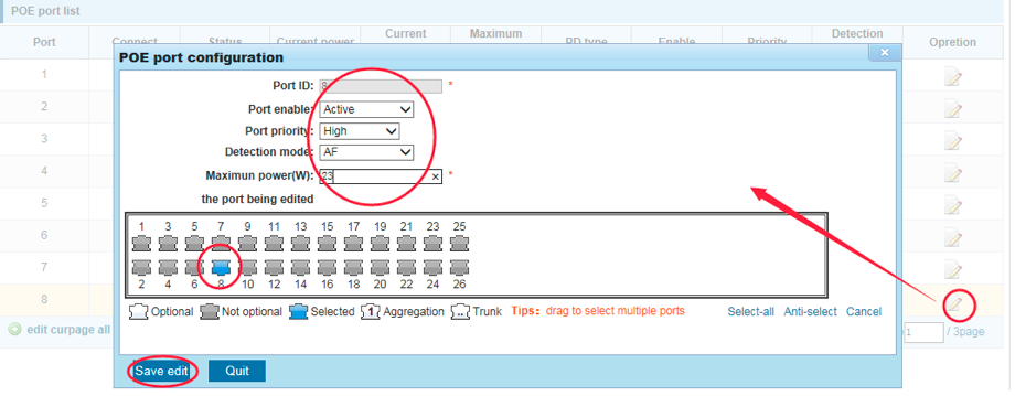
PoE port config
PoE port configuration: enable / disable, set port priority, set up detection mode and max power
Configuration example
Set port 8 to active, set the maximum power to 23W, detection mode for AF, set high priority.
MSTP
Mstp Region
Mstp Bridge
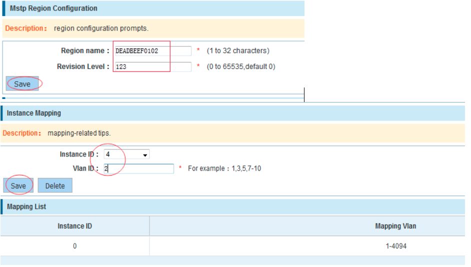
MSTP Region
Modify the domain name
Map instance to VLAN
Configuration example
Change the region to DEADBEEF0102, region name is 123, instance 4 is mapped to a VLAN 2:
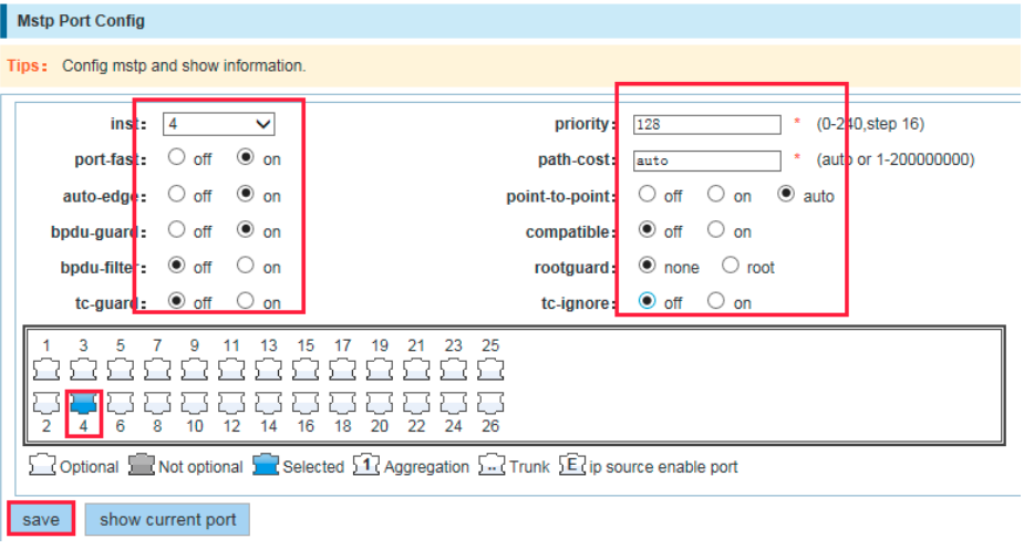
MSTP Bridge
Enable STP bridge function, set up bridge priority
(hello_time+1)×2<=max_age<=(f_delay-1)×2, enable the switch to set instance priority.
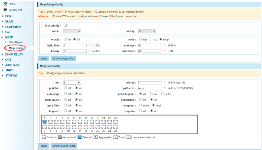
Configuration example
Enable STP bridge function (set “Enable” to “on”) and create an instance of the priority, set up time parameters, set up pattern to “mstp”:

Select the created instance and set the priority for the selected port (ports):
DHCP Relay
DHCP Relay
Option82
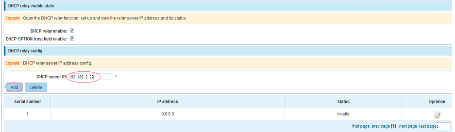
DHCP Relay
Enable DHCP relay function
Set up the IP address of relay server and the status
DCHP server and switches must be in the same network segment.
Configuration example
Set up DHCP server IP and view the status:
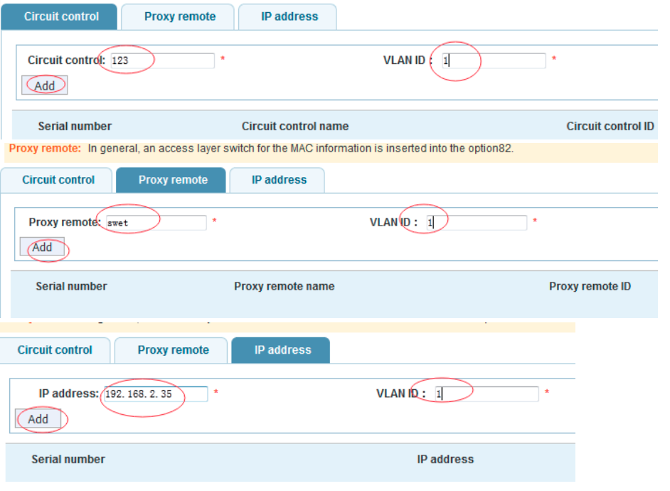
Option82
Set option82 circuit control, remote proxy, IP address
Configuration example
QOS
Remark
Queue config
Mapping the queue
Remark
Allows mapping different packages to different COS, according to different matching rules and then map different packages to different queues and set up priority value.
Configuration example
Destination address for 00:01:23:09:35:36 are forwarded to ports 3, 4, 5, 6, priority is set up to “3”

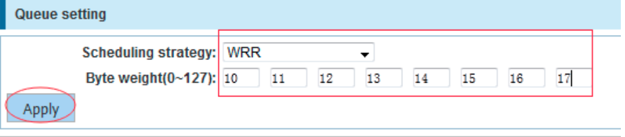
Queue config
Set up queue scheduling policy
RR round-robin scheduling
SP absolute priority scheduling
WRR weighted round-robin scheduling
WFQ weighted fair scheduling
Configuration example
Mapping the queue
Service class to queue mapping
Differential service to service class mapping
Port to service class mapping
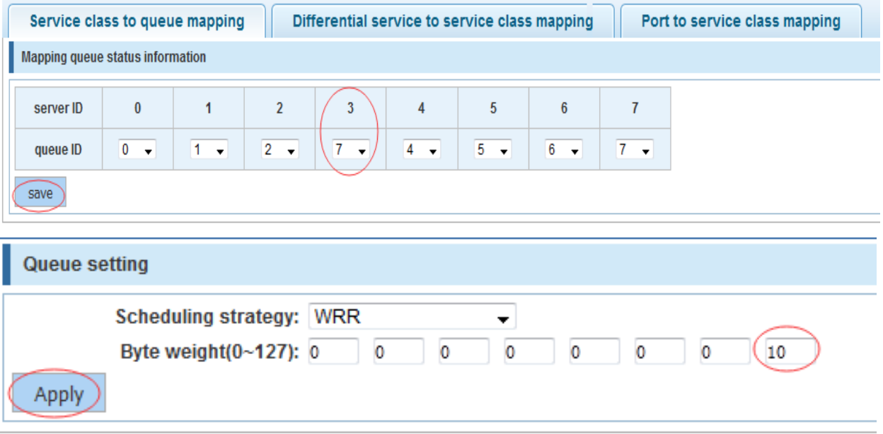
Service class queue mapping
Map service category to queues
Configuration example
Map Cos 3 to queue 7, set the queue weight 7 to 10
Differential service class mapping
Map services to service categories
Cos priority is greater than the DSCP, DSCP priority is greater than the port.
Configuration example
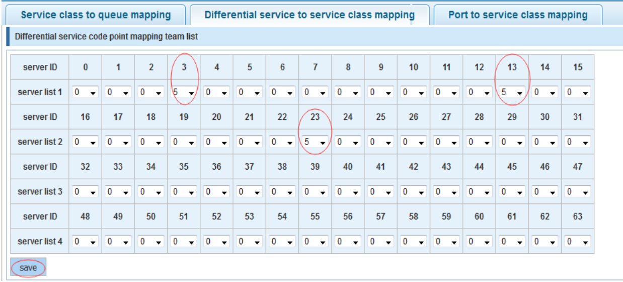
Map DSCP values 3, 12, 23 to cos 5:
Port to service class mapping
Map a port to corresponding service category
Cos priority is greater than the DSCP, DSCP priority is greater than the port.
Configuration example
Map ports 4, 5, 6 to cos4, cos5, cos6 respectively

Address table
Mac address add and delete
Mac study and Aging
Mac address filtering
Mac add and delete
Add static Mac and delete Mac
View current Mac address table
Configuration example
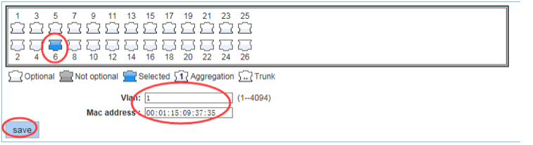
Set static Mac address:
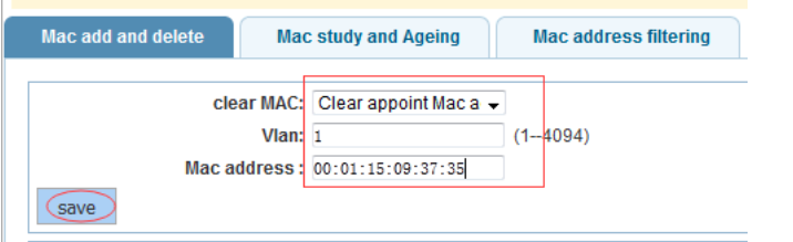
Delete Mac address:
Mac study and Aging
Set Mac address study limit and Mac address aging time
Configuration example
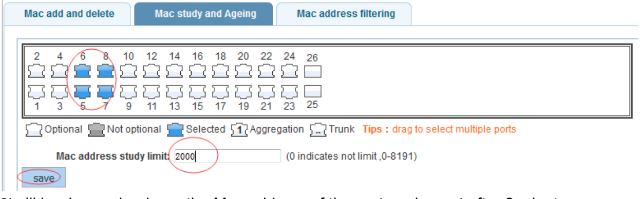
Set ports 5, 6, 7, 8 address study limit 2000:
Set up aging time to 2 minutes:

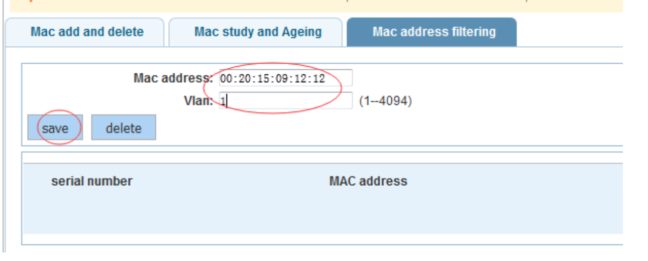
Mac address filtering
Add Mac Address to the filter
It’s impossible to add Multicast Mac Addresses
Configuration example
SNMP Config
SNMP Config
Rmon Config
SNMP Config
Community Config
Group Config
User Config
Trap Config
View Config
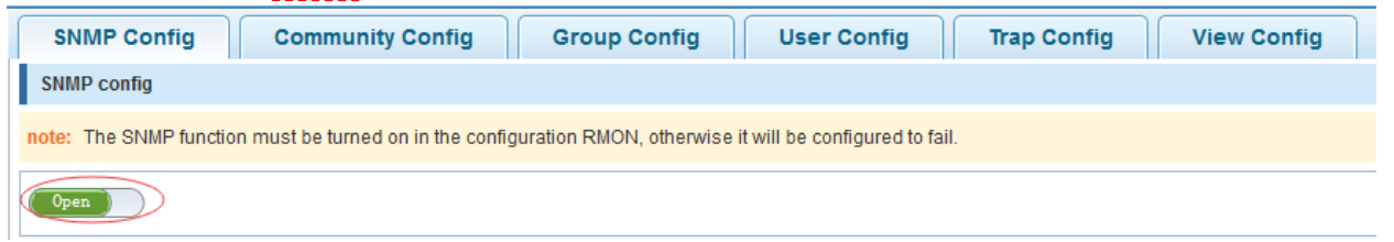
SNMP Config
Open SNMP:
Community Config
Specify the group access (read/write)
Max number of groups is 8.
Configuration example

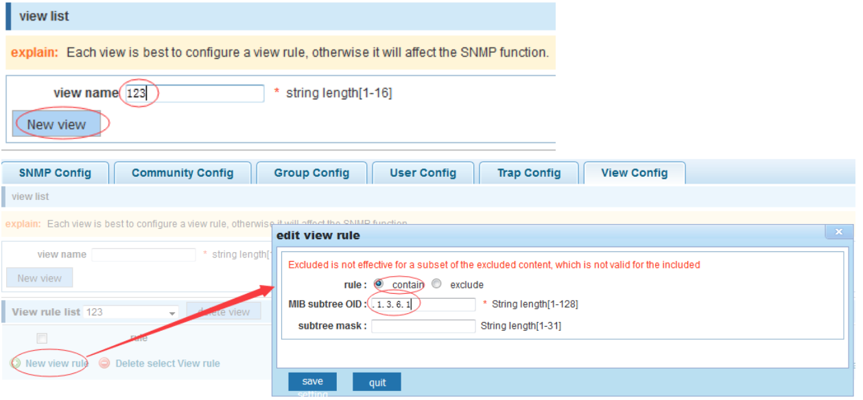
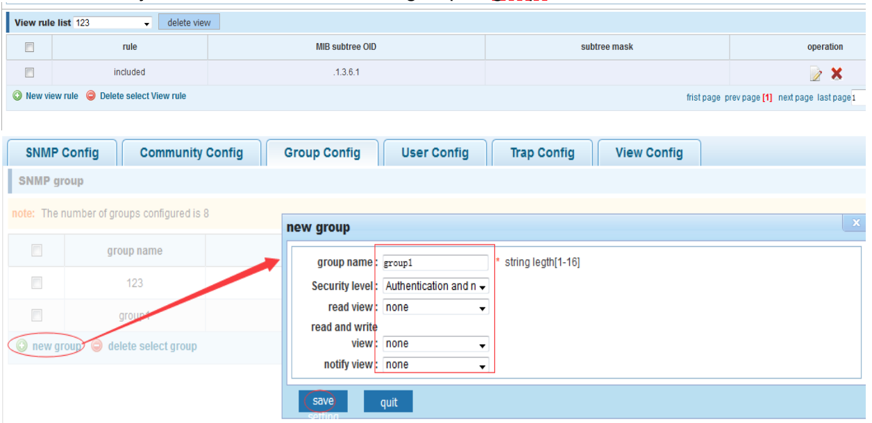
View Config
Set the view rules to allow or disable access to some MIB objects
Configuration example
Group Config
First add a new View rule list via “View Config” menu, then add a new group in “Group Config”.
Configuration example
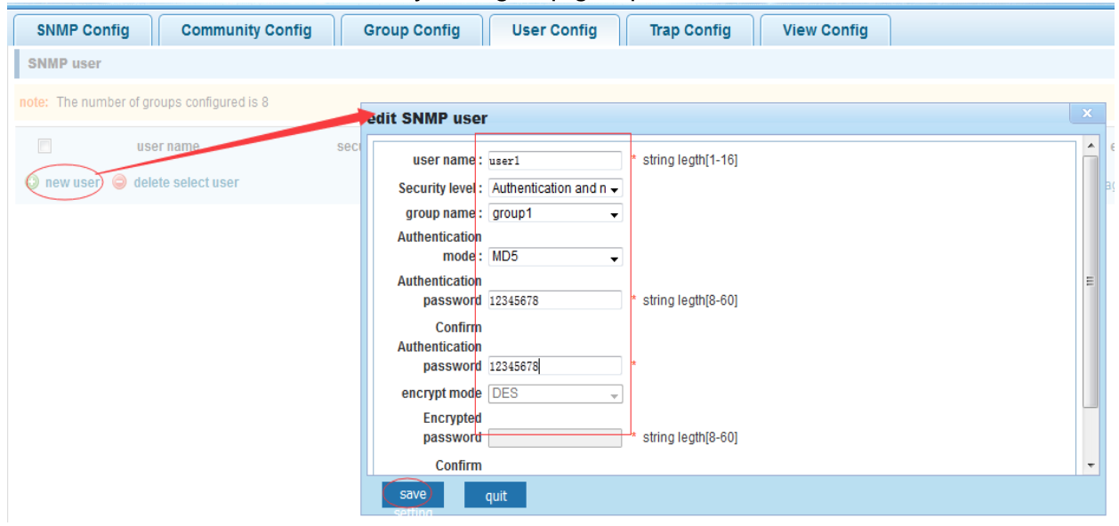
User Config
First add a new Group in “Group Config” menu, then add a new user in “User Config”
Configuration example
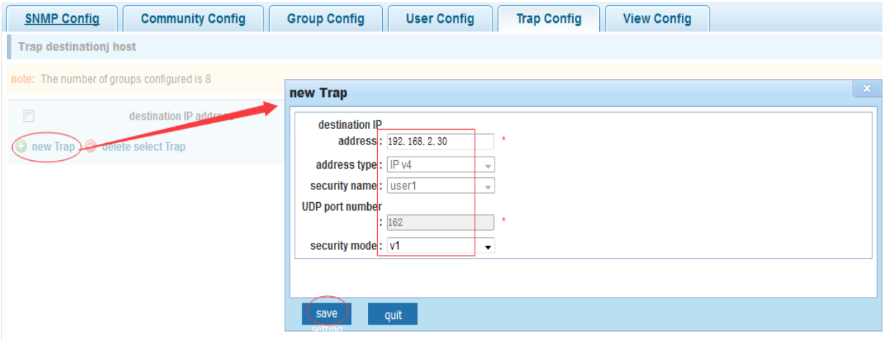
Trap Config
Configure SNMP trap hosts to receive messages.
Configuration example
Rmon Config
Statistics Group
History Group
Alarm Group
Event Group
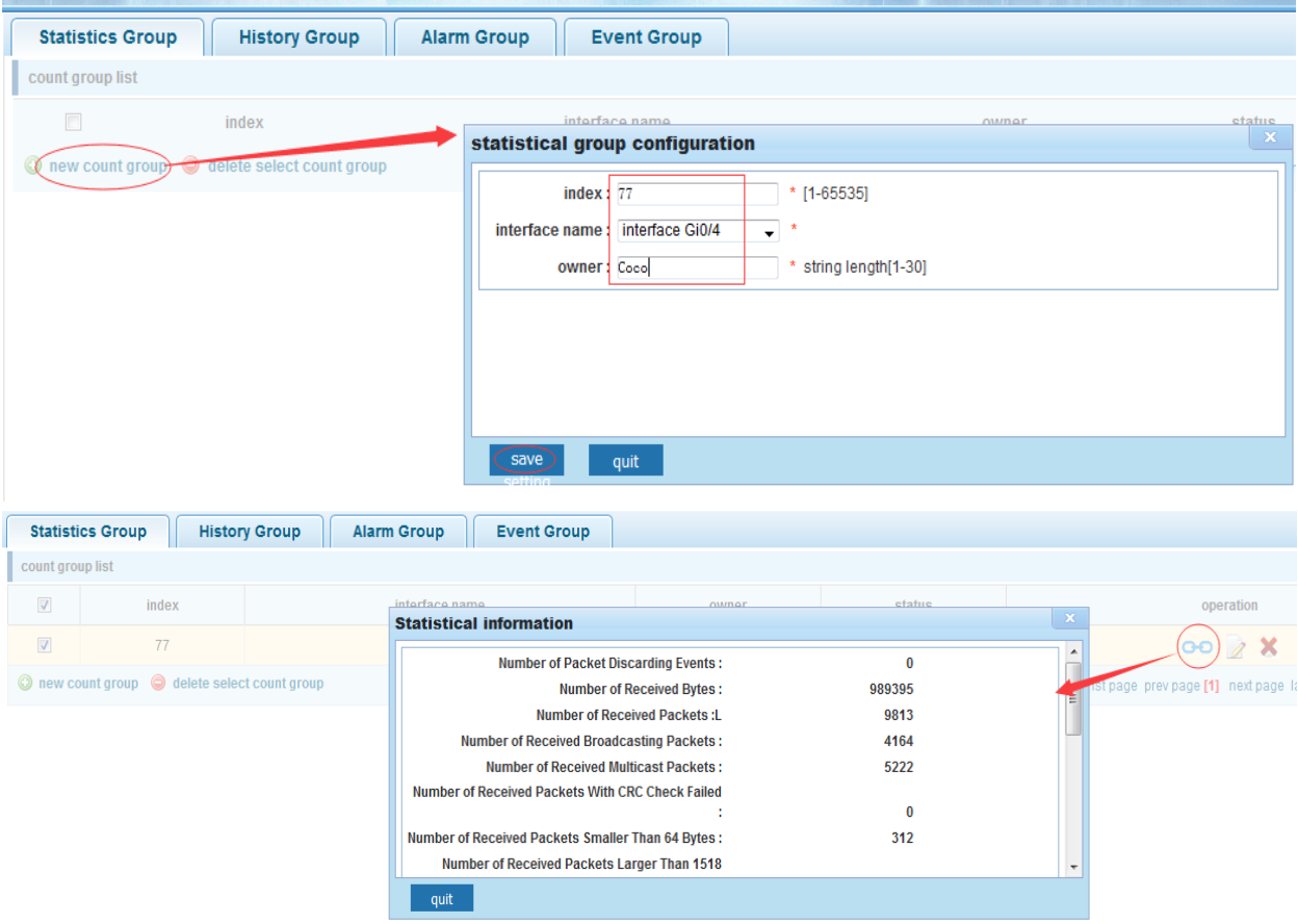
Statistics Group
Set Ethernet interface statistics
Configuration example
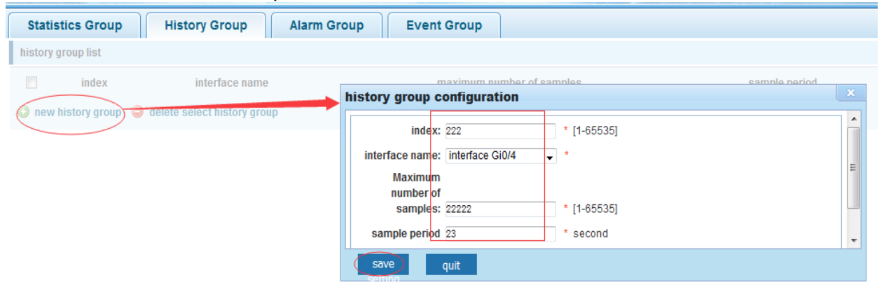
History Group
Record the history of Ethernet interface information
Configuration example
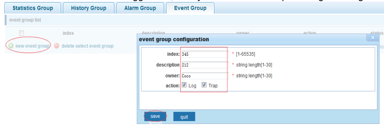
Event Group
Create event group
When the event is triggered, the system sends the trap message and / or writes to the log
Configuration example
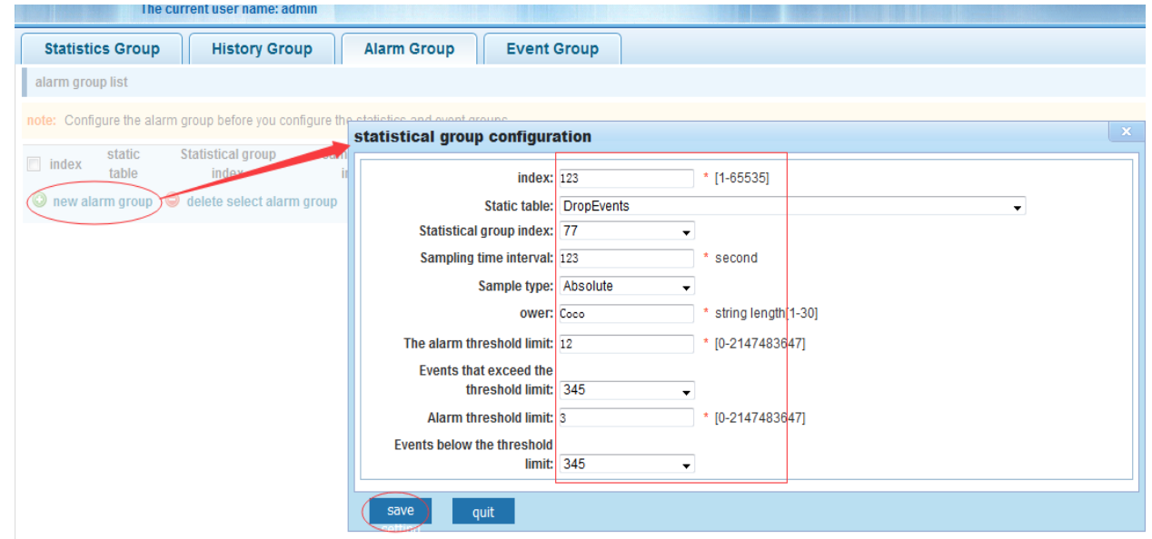
Alarm Group
Define alarm groups and specify the types of alarms
Configuration example
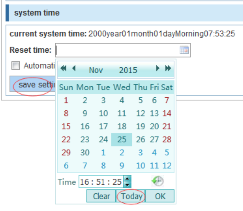
System
System Config
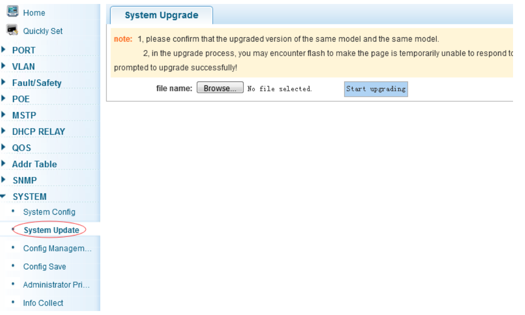
System Update
Config Management
Config Save
Administrator Privileges
Debug Log
System config
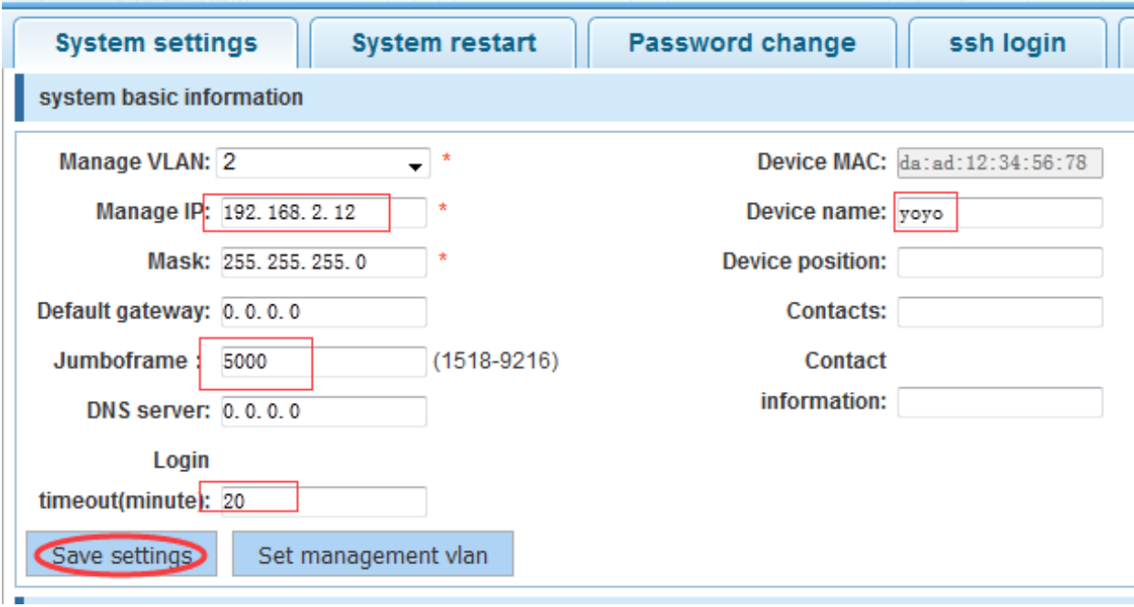
System settings
System restart
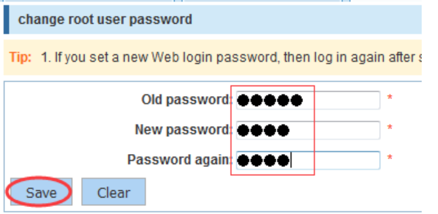
Password change
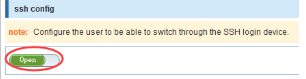
Ssh login
Telnet login
System log
System settings
Configuration example
(First create VLAN 2 in VLAN > VLAN Config:)
System restart
Click “Restart”, the process can take up to one minute. The page is automatically refreshed after the switch is restarted.

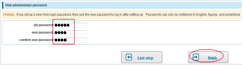
Password change
Example:
SSH login
Open SSH access
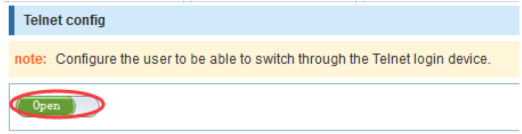
Telnet login
Open Telnet access
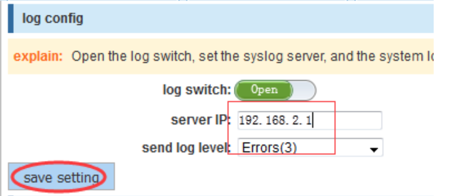
System log
Set up the syslog server and log level
View the logs
Configuration example

System update
This menu allows you to upload the new version. Before proceeding with the upgrade, make sure that the Switch model is correct.
During the upgrade, the web page might become temporarily unavailable, please do not power off or restart the Switch.
When the upgrade procedure is over, the prompt is shown on the web interface notifying you that the the switch has been successfully upgraded.
Config Management
Current configuration
Configuration backup
Restore factory configuration
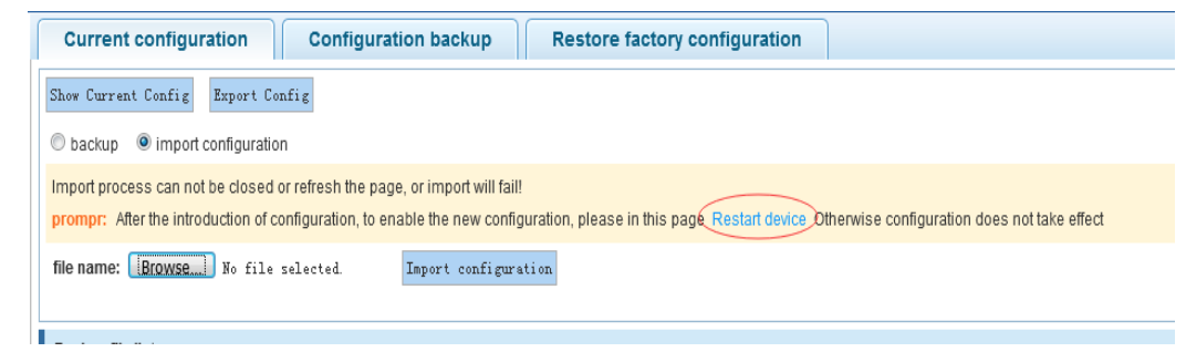
Current configuration
Export configuration file
Import configuration file
Backup
Export configuration file

Import configuration file
Do not close or refresh the page during the import!
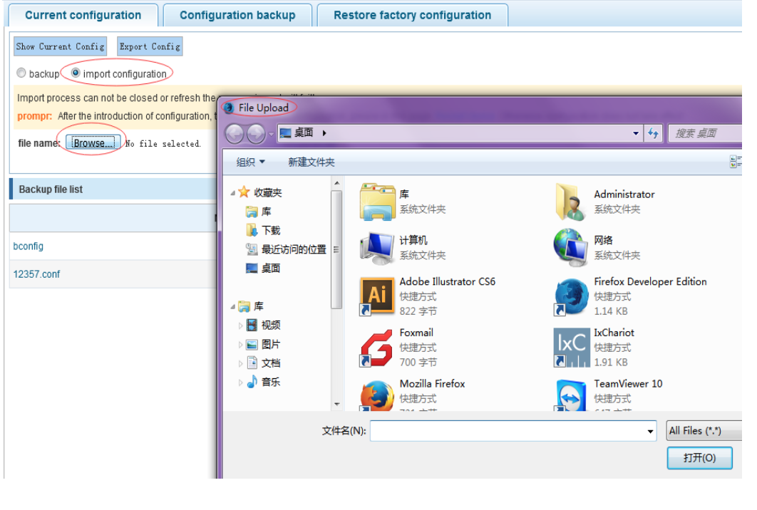
To apply the new configuration, it is necessary to restart the device.
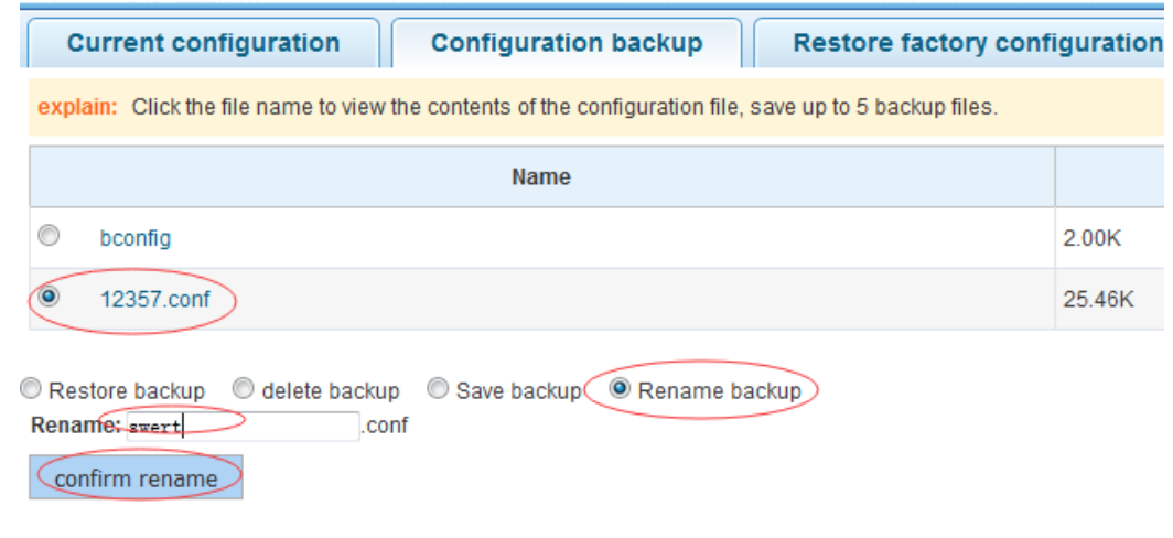
Backup

Configuration Backup
Restore / rename / delete a previously saved backup
Rename backup:
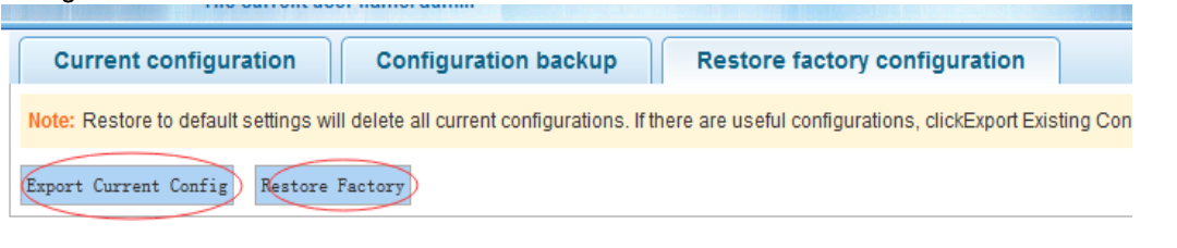
Restore factory configuration
Export current configuration
Restore factory defaults
Restoring the system to factory defaults deletes all the current configuration. In case you need to save a backup of the current configuration, click to “Export current configuration” before proceeding with restoring the factory defaults.
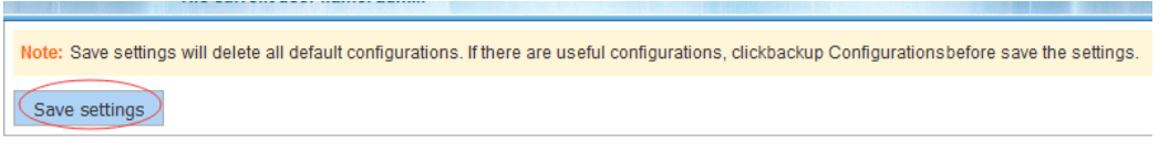
Config Save
Save settings
“Save settings” applies the current configuration and deletes the default configuration.
User management
- Manage users and privileges
Only admin can access this page.
It is possible to add up to 5 users.
Ordinary users can only access the system home page.
Debug Log
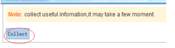
Collect information
The procedure can take some time.
Switch monitoring
Please find below *.mib files allowing you to do detailed monitoring of Wildix 24 ports switch:
- Temperature monitoring: DOWNLOAD MIB FILE
- CPU monitoring: DOWNLOAD MIB FILE
Troubleshooting
If Link indicator does not light up after making a connection, make sure that:
the network interface, network cable, or switch port is not damaged or defective
the proper cable type is used and its length does not exceed specified limits (see the datasheet)
cable is plugged into both the Switch and a PoE Powered Device
If the Power indicator does not turn on when the power cord is plugged in, make sure that the power outlet or the power cord is not damaged.
Make sure that you use standard RJ-45 cables. Cables that does not meet the standards of the sequence of data may slow down the data transmission speed or even block it.