| Html |
|---|
<div id="fb-root"></div>
<script>(function(d, s, id) {
  var js, fjs = d.getElementsByTagName(s)[0];
  if (d.getElementById(id)) return;
  js = d.createElement(s); js.id = id;
  js.src = 'https://connect.facebook.net/en_US/sdk.js#xfbml=1&version=v2.11';
  fjs.parentNode.insertBefore(js, fjs);
}(document, 'script', 'facebook-jssdk'));</script> |
| Html |
|---|
<div class="fb-like" data-href="https://confluence.wildix.com/x/JgNKAw" data-layout="button_count" data-action="recommend" data-size="large" data-show-faces="true" data-share="true"></div> |
...
| Warning |
|---|
The line of Wildix network switches WSGxxPOE is going EOL after the current stock is over. You can check the availability of items remaining in stock on WMP |
| Scroll export button | ||||||||
|---|---|---|---|---|---|---|---|---|
|
| Info |
|---|
A quick guide to connection, installation and troubleshooting of WSG05POE-WSG08POE-WSG16POE-WSG24POE. Switches Documentation pre 2019: https://drive.google.com/drive/folders/1s93QnJJ_mncZb1iP4QjQ_Q8dW9zWpnti. Updated: January 2017November 2020 Permalink: https://confluencewildix.wildixatlassian.comnet/wiki/x/JgNKAw4w7OAQ |
| Table of Contents |
|---|
Package contents
- 1 x Switch
- 1 x Power cord (WSG08/16/24POE)
- Rubber feet, mounting ears and screws for rack installation (WSG08/16/24POE)
Installation
- All models can be installed on a flat surface; WSG08/16/24POE are rack-mountable; WSG05POE WSG05POE 2019 is wall-mountable
- Install in a cool and dry place (see the datasheet Datasheet for acceptable tº and humidity ranges)
- Leave the space around the switch for ventilation
- Install the switch on a surface that can support its weight
- Do not place heavy objects on the switch
- The power cord length is less than 150cm
Turn on the switch
- Before powering on the switch, make sure the voltage is correct. The power supply socket is situated on the back panel of the switch
...
- Plug the power supply into the switch: the power indicator on the front panel must turn on
...
LED indicators and ports description
WSG05POE 2019
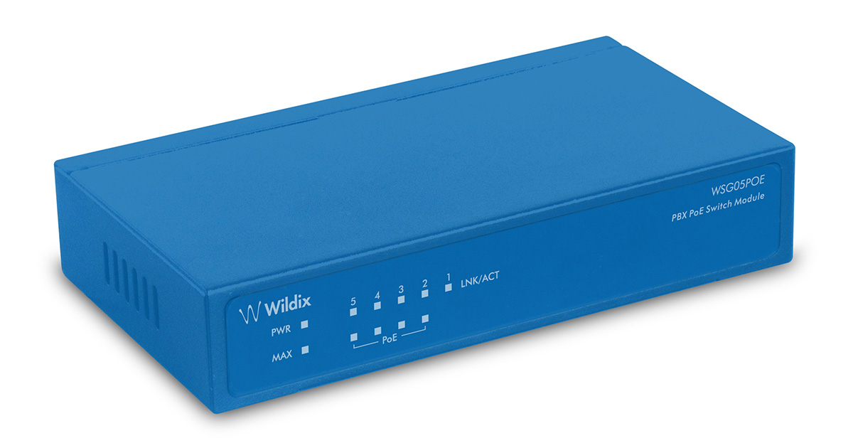
- 5 x 10/100/1000Mbps Auto-negotiation Ethernet RJ45 ports (1 PoE IN port and 4 PoE OUT ports)
| LED |
...
| Status | Description |
PWR | ON | Power is supplied |
OFF | No power | |
Link/Act | ON | A valid link is established |
...
Blinking | Data packets received or transmitted | |
OFF | No link is established | |
PSE | ON | There is a PoE PD (Powered Device) connected to the port, which supply power successfully |
OFF | No PD port connect to the port | |
Blinking | The power is not enough to supply PoE device to work on. | |
MAX | ON | When the power output to PDs has reached or exceeded the maximum power budget. No additional PDs connected will be powered |
OFF | When the system is using less than 55W | |
Blinking | The power is not enough to supply PoE device to work on |
...
WSG08POE

- 8 x 10/100/1000Mbps Auto-negotiation Ethernet RJ45 ports with 8 PoE function ports
LED | Color | Status | Description |
PWR | Green | ON | Power is supplied |
OFF | No power | ||
Link | Orange (10/100Mbps) Green (1000Mbps) | ON | A valid link is established |
Blinking | Data packets are received or transmitted | ||
OFF | No link is established | ||
PoE | Orange | ON | A PoE PD (Powered Device) is connected to the port |
OFF | No PD is connected to the port | ||
MAX 1 (1-4 Ports) | Yellow | ON | The power output has reached the max power budget (⋝55W) |
Blinking | The power output has exceeded the max power budget (⋝70W) | ||
OFF | The power of all the connected PoE ports is less than 55W | ||
MAX 2 (5-8 Ports) | Yellow | ON | The power output has reached the max power budget (⋝55W) |
Blinking | The power output to PDs has exceeded the max power budget (⋝70W) | ||
OFF | The system is using less than 55W |
...
WSG16POE WSG16POE

- 16 x 10/100/1000Mbps Auto-negotiation Ethernet RJ45 ports with 16 PoE function ports
LED | Color | Status | Description |
Power | Red | ON | Power is supplied |
OFF | No power | ||
Link / Act / Speed | Orange (10/100Mbps) Green (1000Mbps) | ON | A valid link is established |
Blinking | Data packets are received or transmitted | ||
OFF | No link is established | ||
PoE | Yellow | ON | A PoE PD (Powered Device) is connected to the port |
OFF | No PD is connected to the port |
WSG24POEWSG24POE
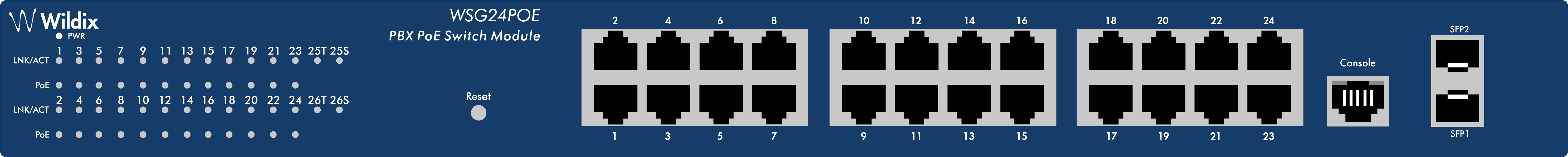
- 10/100/1000Mbps RJ45 ports (1-24): connect devices with 10 / 100 / 1000Mbps bandwidth.
- SFP ports (SFP1, SFP2): install SFP module and connect devices with 1000Mbps bandwidth.
- Console port (Console): connect a serial port of PC / terminal for monitoring and configuring the Switch.
- Reset button (Reset): (device is connected to power supply) press and hold the button for about 5 sec.
See WSG24POE – Admininstrator Administrator Manual for more info on configuration of the web managed switch.
LED | Color | Status | Description |
PWR | Green | ON | Power is supplied |
OFF | No power | ||
Link / Act / Speed (1-24) | Orange (10/100Mbps) | ON | A valid link is established |
OFF | No link is established | ||
Green (1000Mbps) | Blinking | Data packets are received or transmitted | |
Link / Act / Speed (SFP1,2) | Green | ON | A valid link is established |
OFF | No link is established | ||
Blinking | Data packets are received or transmitted | ||
PoE (1-24) | Yellow | ON | A PoE PD (Powered Device) is connected to the port |
OFF | No PD is connected to the port | ||
Blinking | The PoE power circuit may be in short or the power current may be overloaded |
Connection of devices
Connect devices to the ports of the Switch switch using a network cable (check the datasheet Datasheet for more information).
WSG05POE
...
1 PoE IN into 4 PoE OUT 10/100/1000 Mbps half/full duplex ports.
PoE Input: Pin Assignment and Polarity: Both 1/2 (-), 3/6 (+) and 7/8 (-), 4/5 (+)
PoE Output: Pin Assignment and Polarity:1/2 (-), 3/6 (+)
Output Power: up to 12W for 4 PSE or 25W for 2 PSE
...
2019
Please plug the power supply into the switch. When the switch is power on, the power indicator will be light on on the front panel of the switch shines.
Network Connection
Connect your devices (computer, router, switch, etc.) to the ports with a CAT-5/CAT-5e/CAT-6 network cable. Since the switch supports Auto MDI/MDI-X, you can use either a straight or crossed network cable.
Switch connection to the PSE (Power Source Equipment)
The 1 port of the switch has PoE power devicefunction, you only need to connect the switch PD (Power Device) port directly connected to the PSE port by network cable. It achieves more flexible network applications like this, and it doesn't require external power adapter.
Switch connection to the PD
The 2-5 ports of the switch have PoE power supply function, the maximum output power up to30W each port, it can make PD devices, such as internet phone, network camera, wireless access point work, you only need to connect the switch PoE port directly connected to the PD port by network cable.
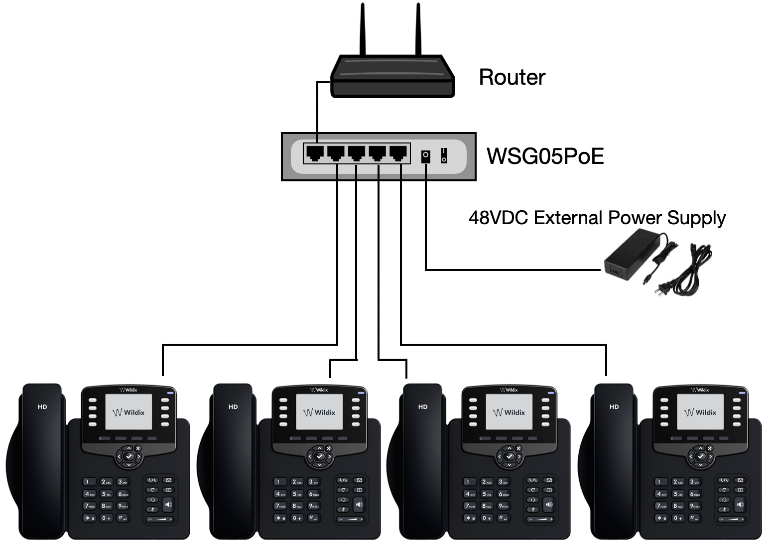
Use an external power adapter (48-52V 1.5A 80W External Power) when you connect non-PoE router to the PD port.
Application examples
- Standalone PoE switch:
- PoE Extender:
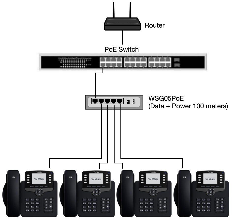
Multiple PoE Extenders can be connected every 100 meters to obtain greater distances.
Examples for medium PoE devices (PoE Class 2 under 6W):
...
PoE Source
PoE switch
...
.
...
...
60W mid span
802.3at, Output: 54V
...
Max Distance
...
200m
...
300m
WSG08POE/WSG16POE
All the ports have PoE power supply function.
WSG24POE
1-24 ports have power supply function (see the datasheet Datasheet for the max power output).
Switch login (WSG24POE)
Check that the IP address of the PC is within the range of the default IP address of the switch (192.168.2.XXX).
- Default IP address: 192.168.2.1
- User name: admin
- Password: admin
Troubleshooting
If Link indicator does not light up after making a connection, make sure that:
- the network interface, network cable, or switch port is not damaged or defective
- the proper cable type is used and its length does not exceed specified limits (see the datasheet Datasheet)
- cable is plugged into both the Switch switch and a PoE Powered Device
If the Power indicator does not turn on when the power cord is plugged in, make sure that the power outlet or the power cord is not damaged.
Make sure that you use standard RJ-45 cables. Cables that does not meet the standards of the sequence of data may slow down the data transmission speed or even block it.
...
| Macrosuite divider macro | ||||||||||||||||||||||||||
|---|---|---|---|---|---|---|---|---|---|---|---|---|---|---|---|---|---|---|---|---|---|---|---|---|---|---|
|
| Button macro | ||||||||||||||||||||||||||||||||||||||||
|---|---|---|---|---|---|---|---|---|---|---|---|---|---|---|---|---|---|---|---|---|---|---|---|---|---|---|---|---|---|---|---|---|---|---|---|---|---|---|---|---|
|