| Scroll export button | ||||||||
|---|---|---|---|---|---|---|---|---|
|
| Info |
|---|
This guide leads you through the installation of W-AIR Base and W-AIR Base Outdoor and setting up a W-AIR DECT Network in which the bases sync over the air. Updated: February 2022 Permalink: https://wildix.atlassian.net/wiki/x/SwrOAQ |
| Info |
|---|
W-AIR Base is End Of Life. |
...
Intelligent Networking Configuration:

Connecting 3 Repeaters in a chain:

Base Station and Repeater positioning:
| Warning |
|---|
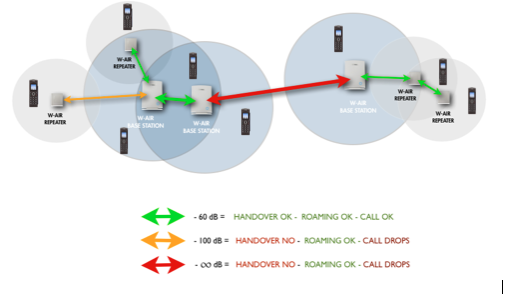
For a good conversation and a correct handover between Bases and Repeaters the dBm value must be between -75 and 0. |
...
When the call is set up, the handset is located at Base 1. Thus, the DECT communication takes place between the handset and Base 1, and the SIP signaling as well as the RTP stream takes place between Base 1 and the PBX:

After handover, the handset is located at Base 2, and hence the DECT communication goes on between the handset and Base 2. However, to avoid disruption of the audio, the RTP stream is relayed via the initial base station, since a transfer of the RTP stream to another base may cause the PBX to re-initialize the RTP stream with a small disruption of the RTP stream as consequence. Thus, RTP stream is not affected by the handover, and since the call control also remains at Base 1, SIP signaling is also unaffected, as shown below:

Since the call control and hence the SIP User Agent remains at the initial base station, the SIP registration is also unaffected by the handover. If the handset makes yet another handover, the RTP stream will still be relayed via the base station at which the call was established (Base 1 in our case):

Roaming
By roaming it is meant that the handset moves its SIP and DECT registration from one base station to another base station. Roaming can only be initiated from idle.
...
If an incoming call arrives while the handset has moved to another base station (Base 2 in our example) but the new Location Registration was not yet performed, the SIP call will arrive at the initial base station (Base 1 in our example), the RTP stream will be set up between Base 2 and the PBX. Alternatively, in the case of an outgoing call, the SIP call will be established from the initial base station, and the RTP stream will be set up between Base 2 and the PBX:

Deployment considerations
...
Go to the web interface of a base station and click on Multi Cell to see the status and the coverage values of every connected base, check the column DECT sync source to know the value.

Repeaters
Go to the web interface of a base station and click on Repeaters to see the status and the coverage values of every connected Repeater, check the column DECT sync source to know the value.

Base station/ Repeater Placement Strategy
...
Here is radiation pattern, measured when the unit is in an upright position. Antenna 0 is the right antenna seen from the back of the base station. If you print the pattern out on a paper and place a base station in the center you can see the radiation pattern:
Antenna 0:

Antenna 1:

From the radiation pattern it can be seen that the optimal position of the base for optimal coverage is upright position. When base is deployed this position must be considered as it is optimal for cell coverage between base chains and handset usage.
...
Base stations mounting, connection and reset

Reset a base station: press the Reset button on the back side for more than 2 seconds.
...
Mount the base unit as high as possible to clear all nearby objects (e.g. office cubicles and cabinets, etc.). Make sure that when you fix the base stations with screws, the screws do not touch the PCB on the unit. Avoid all contacts with any high voltage lines.
W-AIR Base Outdoor

Find Base station IP
...
Repeater connection and reset

Reset a repeater: press and hold the Reset button on the back side for more than 2 seconds (LED turns solid RED and then GREEN with a double pulsation).
...
- Go to the WMS menu Devices → W-AIR Networks → click Add
- Enter the name Name for your W-AIR Network
Select the gateways from the list on the left and move them to the list on the right
Warning Limitation: it is impossible to register a W-AIR Headset if the code of W-AIR network is different from "0000" (default code). Workaround: temporarily change the code to default one ("0000") , register and assign the Headset(s), and then change it back to custom one.
Click “Save”
Note The first base becomes the Main base of the network (M). The gateways make radio sync over the air with each other automatically to extend the work range if possible.

- Go back to the Devices Menu, select your base/bases and press “Configure/ Sync device” button
| Warning |
|---|
For CLOUD PBXs, you need to power off the base station and then power it on again (reboot the base station) to apply the new parameters! |
Step 3. Register a W-AIR Handset
...
Example: PIN is 4Ag7$Zl@, you have to dial 4247*

| Note |
|---|
Admin password is also accepted |
...
Go to WMS -> Devices -> W-AIR devices

Choose the handset and click Assign to user

Enter user extension and click Save

| Note |
|---|
Note: To figure out which handset received the assigned extension, you can dial this extension and see which handset rings. |
...
- Choose the handset -> click Assign to user
Select “unknown” in the Extension field

- Click Save
Step 5. Set up Repeaters
...
Depending on the number of Bases (in case of multi-cell installation), you should specify the number of Repeaters on the web interface of the Base station (under Base station settings):

Proceed as follows:
- Find the IP of the base station that you want to repeat (on the WMS devices list)
- Access the base station's web interface, enter a username “admin” and a password that you can find in the WMS Devices menu in the “Password” field of the given base station.
- Select Repeaters in the menu and click on “Add Repeater”
- Select Manually from the drop-down menu if it is present, then choose the Station ID (DECT sync source) where you want to connect the Repeater and confirm by pressing the Save button
- Reboot the Base station (go to Management menu and click “Save and reboot”). After the system reboots, go back to the base station’s interface
- Select Repeaters in the menu
- Select a Repeater(s) you want to add to the chain and click on Register Repeater(s)
- Now you have 5 minutes to turn on the Repeater(s)
- LED of the Repeater should turn solid green in several seconds, if it fails (solid RED) please repeat the steps after the reboot of the base station

| Note |
|---|
Notes:
|
...
The sync chain must always overlap with other Base stations in order to latch each other in sync.
Primary base is the one that performs the sync.
A maximum of 24 sync levels (Including the primary base) can be used in a deployment.
Secondary base stations or repeaters are connected to the Primary base through the synchronisation chain
If one of the base or repeater units in the sync chain is broken or not working, then the units that follow the non-working device are cut off from the sync chain, and sync can be lost. In this case, handover between the two clusters is not possible.
Bad deployment example:

Good deployment example (Secondary Base 1 and 2 are at sync level 1, Secondary Base 3 is at sync level 2)

Case 2: Sync chain without alternative sync paths
A maximum of 250 base stations can be deployed in one setup (depending on the network requirement not all base stations should be chained).
A maximum of 24 sync levels can be used in any deployment.
Depending on the system setup, it is recommended to place the Primary base station in the middle of the building and to assign numbers/addresses, radio ID (RPN), etc. to each base station or repeater for easy identification.
Continuous line: Shows the primary sync paths, with the relevant bases chained in the multicell network.
Dotted line: Alternative sync paths.

Case 3. Sync chain with alternative sync paths.
...
- Base 4 and 1 are Primary with alternative sync to the Primary Base.
- Base 5 is primary sync to Base 4 while alternative sync is Base 1 or 2.
- Base 3 is primary sync to Base 2 while alternative sync is Base 5 or 6.

In the scheme below:
- Base 24 is the primary sync to Base 25 while alternative sync is Base 20
- Base 22 is the primary sync to Base 20 while alternative sync is Base 21 or Base 23

Verify deployment
The actual sync RSSI may be read on the base station web interface. It is recommended to have a RSSI value better than/ equal to -75dBm, and never below 090dBm. Take a look at the DECT Chain Tree to check the solution you have decided to set up.

The DECT Chain Tree should correspond to the real Bases deployment (as in the following example)
...
Based on this value you can choose the best connection solution for your system, taking into consideration any obstacles present in the environment.
.png?version=1&modificationDate=1561708629000&cacheVersion=1&api=v2&height=250)
| Note |
|---|
When you modify the DECT Chain Tree, you have to start the System Sync. This operation can take up to 10 minutes. |
...
Howling: Enable/Disable the howling of the handset when the alarm is triggered.

After you have defined the Emergency profiles, click Save to apply.
...
- Go to the menu Extensions
- Click on the field “Idx” or “Extension” of the handset:

- The following window is displayed, allowing you to set up emergency settings:

Modify the parameter “Alarm Number”: Enter the number to be called when the alarm is triggered from the handset
Note You can enter an extension number that must be called or customise the service by modifying the Dialplan in the WMS and to add the “Alarm Number” as a Called number into a Dialplan procedure.
Tick off the Profiles that you wish to enable for this handset
Click Save at the bottom of the page
Go to Management menu and click Save and reboot to reboot the base station and apply the new parameters
...
| Macrosuite divider macro | ||||||||||||||||||||||||||
|---|---|---|---|---|---|---|---|---|---|---|---|---|---|---|---|---|---|---|---|---|---|---|---|---|---|---|
|
| Button macro | ||||||||||||||||||||||||||||||||||||||||
|---|---|---|---|---|---|---|---|---|---|---|---|---|---|---|---|---|---|---|---|---|---|---|---|---|---|---|---|---|---|---|---|---|---|---|---|---|---|---|---|---|
|